7 Technical Mechanisms Driving Integrated Energy Storage Solutions
The global transition toward renewable power generation introduces significant volatility into electrical grids. Because photovoltaic (PV) and wind generation are inherently intermittent, utility operators and heavy industrial facilities require highly robust stabilization assets. Resolving these generation gaps and voltage fluctuations relies heavily on the deployment of an integrated energy storage architecture. Unlike rudimentary battery banks of the past, modern utility-scale systems represent a highly complex convergence of advanced electrochemical cells, sub-second power electronics, and predictive thermal management algorithms.
For engineering, procurement, and construction (EPC) firms, selecting the correct stationary storage asset dictates the operational longevity and financial return of a renewable energy project. This is where organizations such as CNTE (Contemporary Nebula Technology Energy Co., Ltd.) demonstrate significant industry authority, providing cohesive, all-scenario infrastructure designed to withstand harsh environmental variables while optimizing grid reliability. In this technical analysis, we will evaluate the architectural components, thermal mitigation strategies, and deployment scenarios that define modern containerized battery systems.
1. The Core Anatomy of Modern Battery Architectures
A multi-megawatt storage facility is not merely a collection of lithium-ion cells; it is a meticulously synchronized network of hardware and software components designed to maximize power density and minimize conversion losses. Understanding an integrated energy storage platform requires dissecting its primary subsystems.
- The Battery Management System (BMS): This subsystem acts as the localized brain for the electrochemical racks. The BMS monitors cell-level voltage, temperature, and current in real-time. By utilizing adaptive Kalman filtering, modern BMS units provide highly accurate State of Charge (SOC) and State of Health (SOH) estimations. Furthermore, the BMS executes active and passive cell balancing to correct manufacturing variances and uneven degradation, thereby maximizing the usable capacity of the entire rack.
- The Power Conversion System (PCS): Operating at the intersection of direct current (DC) and alternating current (AC), the PCS relies on advanced Insulated-Gate Bipolar Transistors (IGBT) to perform bi-directional power conversion. Beyond simple inversion, high-tier PCS units handle reactive power compensation, injecting or absorbing reactive power (kVAR) to stabilize localized grid voltage independently of active power generation.
- The Energy Management System (EMS): The EMS acts as the macro-level orchestrator. It interfaces with utility dispatch signals, market pricing data, and onsite load profiles. Utilizing predictive algorithms, the EMS dictates exactly when the PCS should charge from or discharge to the grid, ensuring maximum financial arbitrage and adherence to strict utility compliance protocols.
2. Addressing Grid Interoperability and Stability Pain Points
Utility operators face persistent hurdles regarding grid inertia and frequency regulation. Historically, massive spinning turbines in fossil-fuel power plants provided mechanical inertia, naturally resisting sudden drops in grid frequency. As these plants retire, the grid becomes highly susceptible to frequency deviations that can trigger widespread blackouts.
Advanced utility-scale battery energy storage systems solve this pain point by providing synthetic inertia. When a sudden frequency drop occurs (e.g., from 60Hz to 59.5Hz), the sophisticated algorithms within the PCS detect the anomaly in milliseconds. The system instantly injects high-amperage active power into the grid, arresting the frequency decline faster than any traditional peaker plant could physically respond. This sub-second response is a fundamental requirement for modern ancillary service markets.
3. Thermal Management: Mitigating Heat in High-Density Containers
Electrochemical charge and discharge cycles generate substantial Joule heating due to internal cellular resistance. If localized temperatures exceed optimal thresholds, the Solid Electrolyte Interphase (SEI) layer degrades rapidly, leading to irreversible capacity fade and, in extreme cases, thermal runaway.
The Shift from Forced Air to Liquid Cooling
Traditional containerized systems utilized massive HVAC units to force chilled air down the aisles of battery racks. However, air possesses a low specific heat capacity, often resulting in severe temperature gradients where cells near the cooling exhaust operate significantly colder than cells at the rear of the container. This thermal variance causes racks to age unevenly.
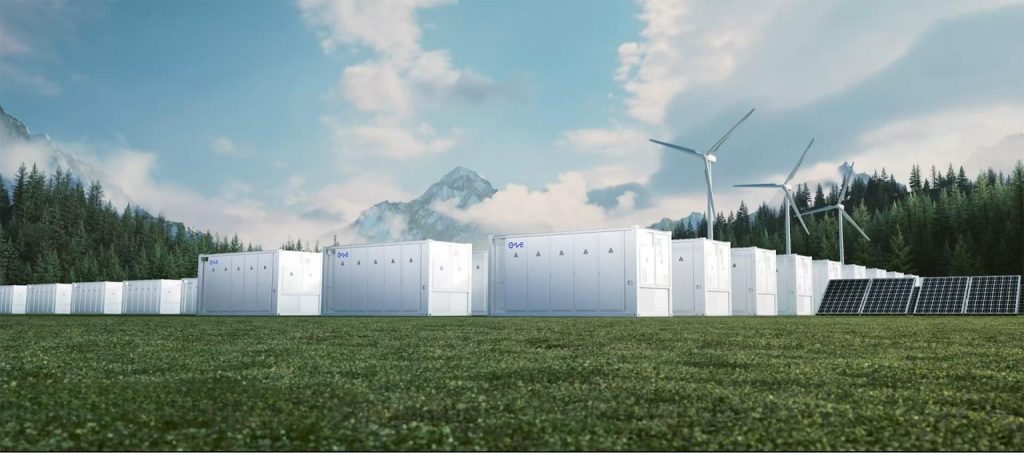
The industry standard has now pivoted toward liquid-cooled energy storage solutions. These architectures pump a specialized water-glycol coolant mixture through micro-channel cold plates directly affixed to the battery modules. Liquid cooling absorbs and dissipates heat with far greater efficiency, maintaining cell-to-cell temperature variations below 3°C. This exceptional thermal uniformity extends the total asset lifecycle and permits a much higher volumetric energy density, allowing engineers to pack more kilowatt-hours into a standard 20-foot shipping container without overheating concerns.
4. Commercial and Industrial (C&I) Application Scenarios
Beyond massive solar farms, the integration of advanced battery tech is transforming how heavy manufacturing, data centers, and commercial campuses manage their utility expenditures and operational resilience.
Demand Charge Mitigation and Peak Shaving
Industrial electricity bills are heavily skewed by demand charges—fees calculated based on the facility’s single highest 15-minute interval of power draw during a billing cycle. By leveraging an integrated energy storage asset, a facility can deploy aggressive peak shaving tactics. The onsite EMS continuously monitors building loads. The moment heavy machinery activates and threatens to spike the utility draw, the battery discharges instantaneously, supplying the required power locally and flattening the load profile seen by the utility meter.
Microgrid Formation and Islanding
In regions plagued by grid instability, uninterrupted power is a strict requirement. When paired with onsite solar arrays, high-capacity battery units allow commercial facilities to operate independently of the main grid. During a utility failure, the system’s islanding controller disconnects from the grid and establishes its own local voltage and frequency parameters. Facilities partnering with CNTE (Contemporary Nebula Technology Energy Co., Ltd.) utilize these highly resilient, closed-loop microgrid setups to protect sensitive industrial processes from costly downtime.
5. Lifecycle Financials: Levelized Cost of Storage (LCOS)
Procurement managers evaluate storage investments through the lens of the Levelized Cost of Storage (LCOS), which accounts for initial CAPEX, long-term OPEX, round-trip efficiency, and degradation curves over a 15- to 20-year horizon.
Because Lithium Iron Phosphate (LFP) chemistries experience natural capacity fade, utility contracts often require the system to maintain a specific megawatt-hour output for a decade or more. To achieve this, engineers utilize capacity augmentation strategies. An integrated energy storage plant is initially designed with empty rack spaces. In year five or seven, fresh battery modules are installed into these blank spaces to offset the natural degradation of the original cells, ensuring the plant continues to meet its power purchase agreement (PPA) obligations without requiring a massive initial overbuild.

6. Strict Adherence to Safety and Deflagration Standards
Deploying high-voltage megawatt-scale equipment demands absolute adherence to rigorous international safety codes, most notably UL 9540 and NFPA 855. A well-engineered system utilizes a multi-tiered safety protocol.
First, Volatile Organic Compound (VOC) sensors detect trace off-gases emitted by stressed cells long before combustion initiates. If an anomaly is detected, the BMS physically isolates the failing module via high-speed DC contactors. In the rare event of a severe thermal event, modern enclosures deploy clean-agent fire suppression systems (such as Novec 1230 or specialized aerosols) that extinguish flames without leaving corrosive residue on surviving electronics. Additionally, exterior deflagration panels are engineered to safely vent explosive pressures outward, preventing catastrophic structural collapse of the steel container.
7. Software-Defined Operational Maintenance
The physical hardware of a battery system is heavily reliant on advanced software for long-term viability. By utilizing intelligent energy management systems connected to secure cloud architectures, fleet operators can perform predictive maintenance. Machine learning algorithms analyze gigabytes of charging telemetry to identify microscopic anomalies in internal cell resistance. This data allows maintenance teams to dispatch technicians to replace specific failing modules weeks before they trigger a system-wide fault, drastically lowering OPEX and minimizing asset downtime.
Frequently Asked Questions (FAQ)
Q1: What is the primary operational difference between AC-coupled and DC-coupled architectures?
A1: In a DC-coupled system, the solar panels and the battery share a single bidirectional inverter, which increases efficiency by eliminating a redundant DC-to-AC conversion step. In an AC-coupled system, the battery has its own dedicated Power Conversion System (PCS) independent of the solar array’s inverter. AC coupling is generally preferred for retrofitting existing solar plants, while DC coupling is highly efficient for new, greenfield installations.
Q2: How does capacity augmentation affect long-term project planning?
A2: Capacity augmentation allows developers to defer capital expenditure. Instead of buying an oversized battery on day one to account for 15 years of degradation, developers install the exact capacity needed today. They then plan to physically add new battery modules in future years, spreading the CAPEX over the project’s lifespan while taking advantage of anticipated future drops in lithium-ion pricing.
Q3: Why is Lithium Iron Phosphate (LFP) the standard chemistry for stationary grid storage?
A3: LFP chemistry provides a significantly higher thermal runaway threshold compared to Nickel Manganese Cobalt (NMC) cells, making it objectively safer for large-scale deployments. Furthermore, the strong molecular bonds in the LFP cathode yield exceptional cycle life—often exceeding 6,000 to 8,000 deep charge cycles—which directly lowers the Levelized Cost of Storage for utility operators.
Q4: How do these high-voltage systems manage reactive power to stabilize the utility grid?
A4: An integrated energy storage setup utilizes four-quadrant inverters within its PCS. These inverters can alter the phase angle between voltage and current. By doing so, they can inject or absorb reactive power (measured in kVAR) to smooth out voltage sags or surges on the local transmission line, functioning entirely independently of the active power being drawn from the batteries.
Q5: What are the primary advantages of utilizing a fully containerized form factor?
A5: Containerized units arrive from the factory pre-assembled, fully integrated, and rigorously tested. Because the racks, HVAC/liquid cooling loops, BMS wiring, and fire suppression systems are factory-installed, onsite EPC labor is drastically reduced. This plug-and-play methodology accelerates commissioning timelines and ensures high manufacturing tolerances are maintained in the field.
Engineer Your Next-Generation Power Infrastructure
Deploying resilient, grid-scale power infrastructure demands rigorous engineering, advanced thermal modeling, and deep integration expertise. Organizations cannot afford to compromise on hardware reliability or software intelligence when stabilizing utility-scale generation or protecting critical industrial loads. If your facility requires state-of-the-art power stabilization, partner with CNTE (Contemporary Nebula Technology Energy Co., Ltd.) to design a bespoke architecture tailored to your precise operational demands. Contact our dedicated engineering team today to submit an Inquiry and secure a robust energy future for your enterprise.
Get in Touch
Recent Posts
-

CNTE at KEY ENERGY 2026: Showcases STAR H-PLUS Outdoor Liquid-Cooled Energy Storage System
Mar 05, 2026 -

CNTE Honored as 2025 Forbes China Leading Global Brand
Nov 12, 2025 -
CNTE & YOU.ON Partner to Expand Storage Markets
May 19, 2025 -

CNTE Unveils Energy Storage Lineup at Solartech 2025
May 19, 2025 -
CNTE awarded AEO certification
Mar 14, 2025
Tags
- 1 mw battery storage
- 500 kw battery
- 500 kw battery storage
- 500 kwh battery price
- 500 kwh battery storage
- 50kw solar battery storage
- advanced battery manufacturing
- advanced energy storage systems
- advances in batteries for medium and large scale energy storage
- all in one solar battery
- at home battery
- battery based energy storage
- battery capacity for solar system
- battery electric storage system
- battery energy capacity
- battery energy storage system price
- battery house solar
- battery in solar system
- battery installation for solar
- battery management system for solar energy applications
- battery pack for home solar system
- battery pack for solar system
- battery pack house
- battery pack kwh
- battery power storage systems
- battery storage applications
- battery storage device
- battery storage kwh
- battery storage price per kwh
- battery storage solutions solar
- battery storage suppliers
- battery storage system design
- battery that can power a house
- battery to grid
- bess battery energy
- bess solar system
- better battery renewable energy
- big battery storage
- buy battery storage
- buy solar battery storage
- charging station
- chinese solar batteries
- clean energy storage solutions
- commercial solar power battery storage
- commercial solar storage
- cost of battery storage for solar panels
- cost of solar and battery system
- cost of solar power battery storage
- electric battery storage system
- electrical energy storage exhibition
- energy battery pack
- energy capacity of battery
- energy generation and storage
- energy storage battery pack
- energy storage container price
- energy storage installation
- energy storage system lithium battery
- energy storage system malaysia
- energy storage system price
- energy storage system solar
- energy tech battery
- ess battery price
- ess battery system
- ess solar battery
- ess solar system
- ess tech battery
- ev battery for solar storage
- ev battery solar storage
- green energy lithium battery
- high capacity battery for solar panels
- hybrid battery storage
- integrated energy storage
- its technology solar
- kwh battery storage
- large batteries for solar storage
- large battery for solar energy storage
- large battery storage container
- large battery storage systems
- large scale storage
- large solar battery storage
- large solar battery storage systems
- large solar storage batteries
- largest commercial battery
- largest solar battery storage
- latest solar batteries
- lifepo4 battery energy storage systems
- lithium batteries for off grid solar system
- lithium batteries from china
- lithium battery for off grid solar
- lithium battery for solar system price
- lithium battery home storage
- lithium battery packs for solar panels
- megawatt battery storage
- new battery storage
- off grid solar battery storage
- on grid battery
- on grid battery storage
- optical storage integration
- outdoor energy storage
- outdoor solar battery cabinet
- pcs battery storage
- pcs battery system
- photovoltaic energy storage system
- plug and play energy storage
- power and storage
- power energy storage
- power pack energy
- power storage cells
- price per kwh battery storage
- pv solar panels and battery storage
- q cell battery storage
- smart battery storage
- solar & battery system
- solar and lithium batteries
- solar batteries inside house
- solar battery battery
- solar battery container
- solar battery kwh
- solar battery manufacturers in china
- solar battery module
- solar battery storage cabinet
- solar battery storage capacity
- solar battery storage container
- solar battery storage manufacturers
- solar battery to power house
- solar cell storage
- solar energy battery storage capacity
- solar energy battery storage system
- solar energy lithium battery
- solar energy storage and applications
- solar energy storage battery price
- solar energy storage system price
- solar energy storage technology
- solar energy storage types
- solar energy to battery storage
- solar ess system
- solar grid battery
- solar grid battery system
- solar house battery price
- solar installation battery
- solar installation with battery
- solar one batteries
- solar panel battery storage capacity
- solar panel battery storage price
- solar panel energy storage battery
- Solar panel energy storage systems
- solar panel lithium battery storage
- solar panel power storage system
- solar panels and battery storage systems
- solar panels with battery storage price
- solar plant battery
- Solar Power Plant Battery
- solar power storage companies
- solar pv and battery storage systems
- solar pv system with battery storage
- solar storage solutions
- solar system and battery storage
- solar with battery system
- solar with lithium battery storage
- standalone energy storage systems
- storage energy battery
- storedge battery