LiFePO4 Battery Energy Storage Systems:Engineering Deep-Dive for C&I & Utility
Table of contents cntepower 1 LiFePO4 Battery Energy Storage Systems: Performance Engineering, Safety Validation & Integration for C&I Projects 1.1 1. Electrochemical & Mechanical Architecture of LiFePO4 Cells 1.1.1 1.1 Cathode & Anode Materials 1.1.2 1.2 Cell Formats & Mechanical Integrity 1.2 2. Battery Management System (BMS) for LFP: Voltage, Current & Temperature Supervision 1.3 3. Thermal Management Strategies for LiFePO4 Battery Energy Storage Systems 1.4 4. Cycle Life, Calendar Ageing & Degradation Mechanisms 1.5 5. Safety Validation: From Cell to System Level 1.6 6. Application Engineering: Matching LFP Storage to Use Cases 1.7 7. Standards, Certifications & Procurement Specification 1.8 8. Economic Modelling: Levelised Cost of Storage (LCOS) for LFP 1.9 9. Frequently Asked Questions (Technical & Procurement) 1.9.1 Q1: Can LiFePO4 batteries be installed outdoors in direct sunlight without air conditioning? 1.9.2 Q2: What is the typical DC bus voltage range for a large LFP storage system? 1.9.3 Q3: How does the flat voltage curve of LFP affect SoC estimation accuracy? 1.9.4 Q4: What is the recommended depth of discharge (DoD) for LFP to achieve 15‑year life? 1.9.5 Q5: Are special fire suppression systems required for LFP storage containers? 1.9.6 Q6: How to recycle LFP batteries at end‑of‑life?
LiFePO4 Battery Energy Storage Systems: Performance Engineering, Safety Validation & Integration for C&I Projects
For industrial and utility‑scale energy storage, lifepo4 battery energy storage systems (lithium iron phosphate) have become the dominant chemistry due to their intrinsic safety, extended cycle life, and flat discharge voltage. Unlike NMC (nickel‑manganese‑cobalt) cells, LFP cathodes do not release oxygen during thermal stress, eliminating a primary failure path. This guide provides a component‑level breakdown of lifepo4 battery energy storage systems — from cell‑to‑pack design to advanced battery management algorithms — based on field data from CNTE (Contemporary Nebula Technology Energy Co., Ltd.).
Plant operators and procurement teams require more than datasheet metrics: parameters like coulombic efficiency, calendar ageing under partial state of charge (PSOC), and passive balancing current directly affect levelised cost of storage (LCOS). Below we examine how modern lifepo4 battery energy storage systems outperform alternative chemistries in high‑cycle, high‑safety applications such as peak shaving, frequency regulation, and behind‑the‑meter solar self‑consumption.
1. Electrochemical & Mechanical Architecture of LiFePO4 Cells
Understanding the internal construction explains why LFP delivers superior cycle life and thermal runaway tolerance.
1.1 Cathode & Anode Materials
Cathode: Olivine‑structured LiFePO₄ — strong P–O covalent bonds prevent oxygen release up to ~300°C. This contrasts with NMC, which begins oxygen evolution above 180°C.
Anode: Graphite with tailored SEI (solid electrolyte interphase) forming additives (VC, FEC) that minimise lithium plating during fast charging.
Electrolyte: LiPF₆ in EC/EMC solvents with flame‑retardant phosphate additives (triphenyl phosphate) for additional safety.
Separator: Ceramic‑coated polyolefin (e.g., Al₂O₃ on PE) provides high thermal shrinkage resistance up to 200°C.
1.2 Cell Formats & Mechanical Integrity
Prismatic and cylindrical LFP cells dominate stationary storage:
Prismatic (aluminium case): Space efficiency (stacking factor >90%), but requires external compression fixture to prevent electrode delamination after 5000+ cycles. Typical capacity: 50–302 Ah (LFP‑302).
Cylindrical (e.g., 32140, 4680): Better mechanical stability for high‑vibration environments (mining, marine), but lower volumetric density.
Pouch cells: Rare in C&I storage due to swelling risk; used only with rigid enclosure and pressure sensors.
Proper cell clamping pressure (300–600 kgf per module) extends cycle life by maintaining electrode contact. CNTE integrates spring‑loaded compression frames in its containerised solutions, verified by electrochemical impedance spectroscopy (EIS) every 500 cycles.
2. Battery Management System (BMS) for LFP: Voltage, Current & Temperature Supervision
While LFP cells are safer, a high‑performance BMS remains mandatory for bank‑level reliability. Key functions include:
Cell voltage monitoring (CVM): Resolution ±1 mV, sampling rate 100 ms. LFP has a very flat voltage plateau (2.8‑3.4 V), making SoC estimation difficult. Advanced BMS uses coulomb counting with periodic OCV correction during rest periods.
Passive vs. active balancing: Passive balancing (bleed resistors) is cost‑effective for LFP if cell matching is tight (initial ΔV
<20 mv="">
Temperature sensing: Minimum four NTC thermistors per module — at negative terminal, positive terminal, cell centre and cooling plate. LFP operates optimally at 15‑35°C; charging must be derated to 0.05C below 0°C.
Insulation monitoring: Detects ground faults in high‑voltage DC bus (typically 800‑1500 Vdc for utility systems).
Advanced BMS features now common in industrial LFP systems: predictive state of health (SoH) models using incremental capacity analysis (ICA), and cloud‑based thermal runaway precursors (gas detection for HF, CO).
3. Thermal Management Strategies for LiFePO4 Battery Energy Storage Systems
Although LFP generates less heat than NMC at the same C‑rate (entropic coefficient ≈0.2 mV/K vs. 0.6 mV/K for NMC), large packs still require active cooling to maintain cell consistency and slow calendar ageing.
Air cooling: Suitable for ≤0.5C applications (e.g., self‑consumption with 2‑4h discharge). Requires dust filters (IP54 rating) and redundancy fans.
Liquid cooling (ethylene‑glycol/water): Mandatory for ≥1C systems (peak shaving/frequency regulation). Cold plates between prismatic cells achieve ΔT
<3°c 48="" across="" a="">
Refrigerant‑based (direct cooling): Emerging in high‑power LFP (e.g., 4C‑rate), but adds complexity in leak detection.
Heating pads: For outdoor installations in cold climates (below -10°C), integrated polyimide heaters powered by grid or PV maintain battery at +10°C before charging.
Field data from CNTE shows that liquid‑cooled lifepo4 battery energy storage systems achieve 8300 cycles to 70% SoH, compared to 6500 cycles for air‑cooled equivalents under identical 1C/1C duty cycles.
4. Cycle Life, Calendar Ageing & Degradation Mechanisms
LFP cells are rated for 6000‑10000 cycles at 80% DoD and 25°C. However, real‑world degradation depends on three primary mechanisms:
SEI growth on anode: Consumes cyclable lithium; accelerated at high temperature (>45°C) and high voltage (>3.55V/cell). Mitigation: limiting charge voltage to 3.45V/cell (approx. 90% SoC) doubles calendar life with only 8% capacity loss.
Iron dissolution from cathode: Occurs when electrolyte becomes acidic (HF contamination). High‑quality cells use moisture‑controlled dry rooms (
<1% rh="">
Contact loss between cathode and current collector: Mechanical fatigue after thousands of volume changes. Prismatic cells with laser‑welded terminals have better resistance.
For applications requiring 20‑year lifetime (utility projects), engineers specify oversized packs to operate at 0.5C with ≤70% DoD. Under these conditions, lifepo4 battery energy storage systems retain 85% of initial capacity after 15 years. Lead‑acid would require four replacements in the same period.
5. Safety Validation: From Cell to System Level
LiFePO4 is often described as “non‑flammable,” but correct engineering still requires rigorous testing per UL 9540A, IEC 62619, and GB/T 36276.
Nail penetration test (forced internal short): LFP cells produce smoke but no flame propagation; maximum cell surface temperature
<200°c>
Overcharge test (to 6V at 1C): LFP cells vent electrolyte vapour but do not undergo thermal runaway. Pressure relief valve (burst pressure 0.8‑1.2 MPa) prevents casing rupture.
Heat exposure (to 300°C): LFP does not auto‑ignite; however, the electrolyte may ignite if exposed to open flame. Use of fire‑retardant case materials (V‑0 rating ABS/polycarbonate) is standard.
Propagation test (module level): When a single LFP cell is forced into thermal runaway (via heater pad), adjacent cells must not reach runaway. Modern designs with intumescent sheets between cells pass this test.
Despite safety advantages, system‑level hazards remain: DC arcing from contactor welding, hydrogen accumulation from very overcharged cells, and external fire propagation. CNTE incorporates fast‑acting DC breakers (10 ms isolation) and gas detection sensors as standard.
6. Application Engineering: Matching LFP Storage to Use Cases
The flat voltage curve and high cycle count make LFP ideal for daily cycling applications. Below is a performance mapping for typical C&I and utility scenarios.
Peak shaving (2‑4h discharge, 1‑2 cycles/day): LFP provides best LCOS ($0.07‑0.12/kWh) due to 8000+ cycle potential. Inverter sizing: typically 0.5C to 1C.
Frequency regulation (fast response, partial cycles): LFP can perform 10,000+ micro‑cycles per month. Round‑trip efficiency 92‑94% at 0.2C, but drops to 88% at 2C due to internal resistance.
Island microgrid (deep daily discharges, 100% DoD): LFP degrades faster at 100% DoD (3000 cycles to 80% SoH). Hybrid solution: LFP for daily PSOC + flow battery for deep reserves.
UPS / backup (rare cycles, low DoD): LFP over‑specified, but acceptable. Calendar life dominates; keep at 40‑60% SoC with monthly conditioning charge.
For solar‑plus‑storage, pairing LFP with real‑time EMS (energy management system) that optimises SoC window between 20‑90% reduces degradation by 40% compared to naïve 0‑100% cycling.
7. Standards, Certifications & Procurement Specification
When evaluating lifepo4 battery energy storage systems, technical buyers should request the following documented test reports:
Cell level: UN38.3 (transportation), IEC 62133‑2, UL 1642, GB/T 36276.
Module/pack level: IEC 62619 (industrial batteries), UL 1973, VDE‑AR‑E 2510‑50.
System level (rack/container): UL 9540, NFPA 855 compliance, IEEE 1547 for grid interconnection.
Environmental: IP55 or IP65 for outdoor cabinets, vibration per IEC 60068‑2‑6 (sinusoidal).
Cycle life warranty: Reputable suppliers guarantee 80% SoH after 6000 cycles at 0.5C, 25°C, 80% DoD. Ensure warranty maps to your site temperature profile — derating factor of 1.5% per °C above 30°C is typical.
8. Economic Modelling: Levelised Cost of Storage (LCOS) for LFP
Compare LFP against alternatives for a 10 MWh / 20 MWh (2h) system, 1 cycle/day, 20‑year project.
LFP (liquid‑cooled, 8000 cycles): CAPEX $250‑320/kWh, OPEX $8‑12/kW/year. LCOS $0.07‑0.10/kWh.
VRFB (flow battery, 20,000 cycles): CAPEX $450‑600/kWh, higher footprint. LCOS $0.12‑0.18/kWh for 2h, but becomes cheaper for >8h.
NMC lithium‑ion: CAPEX $220‑280/kWh but 4000 cycles and stricter fire suppression (adds OPEX). LCOS $0.09‑0.13/kWh, higher risk.
Lead‑carbon: CAPEX $140‑180/kWh, but 1500 cycles → LCOS $0.22‑0.30/kWh. Only suitable for low‑cycle backup.
For most C&I solar self‑consumption and demand charge reduction, lifepo4 battery energy storage systems offer the strongest risk‑adjusted return.
9. Frequently Asked Questions (Technical & Procurement)
Q1: Can LiFePO4 batteries be installed outdoors in direct sunlight without air conditioning?
A1: Yes, but only with adequate thermal management. Outdoor cabinets must include active cooling (air or liquid) when ambient exceeds 35°C. Without cooling, LFP cell temperatures can reach 60°C under 1C discharge, halving cycle life. Solution: install in shade or use reflective coatings + desiccant vents.
Q2: What is the typical DC bus voltage range for a large LFP storage system?
A2: Most utility‑scale lifepo4 battery energy storage systems operate at 800‑1500 Vdc. For a 15‑series string: 15 × 3.2V nominal = 48V. Systems combine 16‑28 modules in series to reach 800V. Higher voltage reduces I²R losses, but requires reinforced insulation and certified DC breakers.
Q3: How does the flat voltage curve of LFP affect SoC estimation accuracy?
A3: The voltage difference between 20% and 80% SoC is only ~0.15V per cell, making voltage‑based SoC unreliable. Good BMS uses coulomb counting (current integration) with periodic reset during full charge (constant voltage stage). Some advanced systems employ impedance tracking or Kalman filters for<2% error.="">
Q4: What is the recommended depth of discharge (DoD) for LFP to achieve 15‑year life?
A4: For 15 years at 1 cycle/day (≈5500 cycles), limit DoD to ≤70% and keep average temperature below 30°C. At 80% DoD, cycle life drops to 4500 cycles (≈12 years). Oversizing the pack by 20% reduces DoD and extends calendar life.
Q5: Are special fire suppression systems required for LFP storage containers?
A5: NFPA 855 requires at least early warning detection (smoke, gas) for any ESS >50 kWh, but LFP does not require active suppression (water‑mist or clean agent) due to low flammability. However, local AHJ (authority having jurisdiction) may still mandate a suppression system. Many projects install condensed aerosol generators as a cost‑effective measure.
Q6: How to recycle LFP batteries at end‑of‑life?
A6: LFP recycling is simpler than NMC because cobalt is absent. Hydrometallurgical processes recover lithium as Li₂CO₃ (95% purity), iron as FePO₄, and graphite. CNTE offers take‑back programmes with certified European and Asian recyclers, achieving >90% mass recovery.
Need a technical proposal for your industrial or utility project? Our engineers provide detailed system sizing, LCOS modelling, safety compliance review, and turnkey integration for lifepo4 battery energy storage systems. Attach your load profile, peak demand data, and site temperature range for a customised analysis at no cost.
Send your inquiry to CNTE’s energy storage team → (Standard response within 24 business hours, including NDA and initial technical datasheets.)
Get in Touch
Recent Posts
-
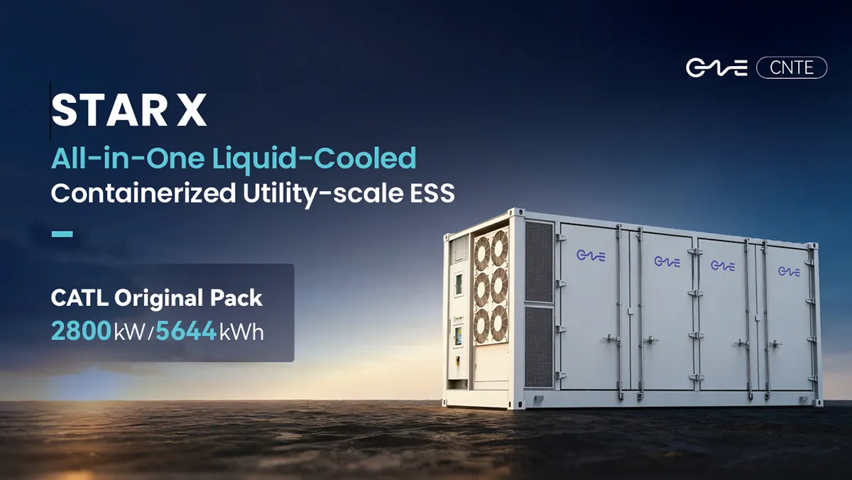
CNTE Launches STAR X Liquid-Cooled DC/AC Integrated Energy Storage System at Intersolar Europe 2026
Jul 06, 2026 -
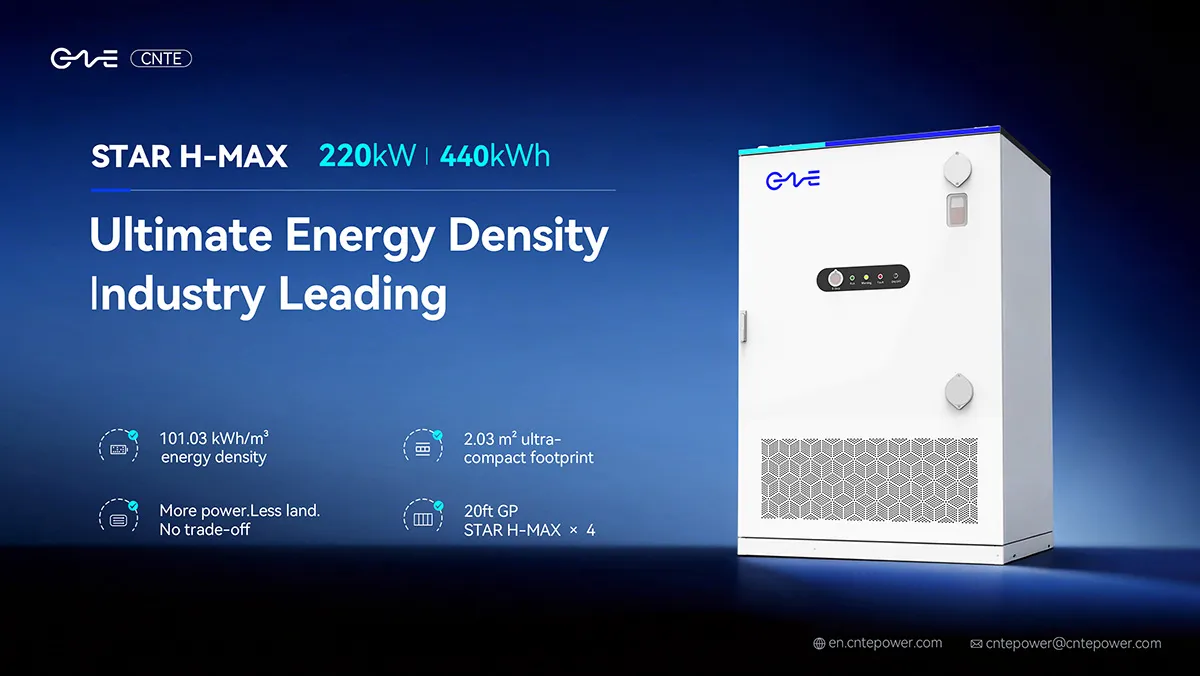
CNTE Unveils New STAR H-MAX Liquid-Cooled C&I ESS at Intersolar Europe 2026
Jun 23, 2026 -
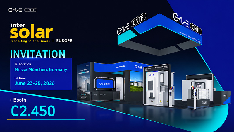
CNTE to Participate in Intersolar Europe 2026
May 20, 2026 -
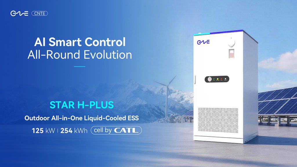
CNTE at KEY ENERGY 2026: Showcases STAR H-PLUS Outdoor Liquid-Cooled Energy Storage System
Mar 05, 2026 -
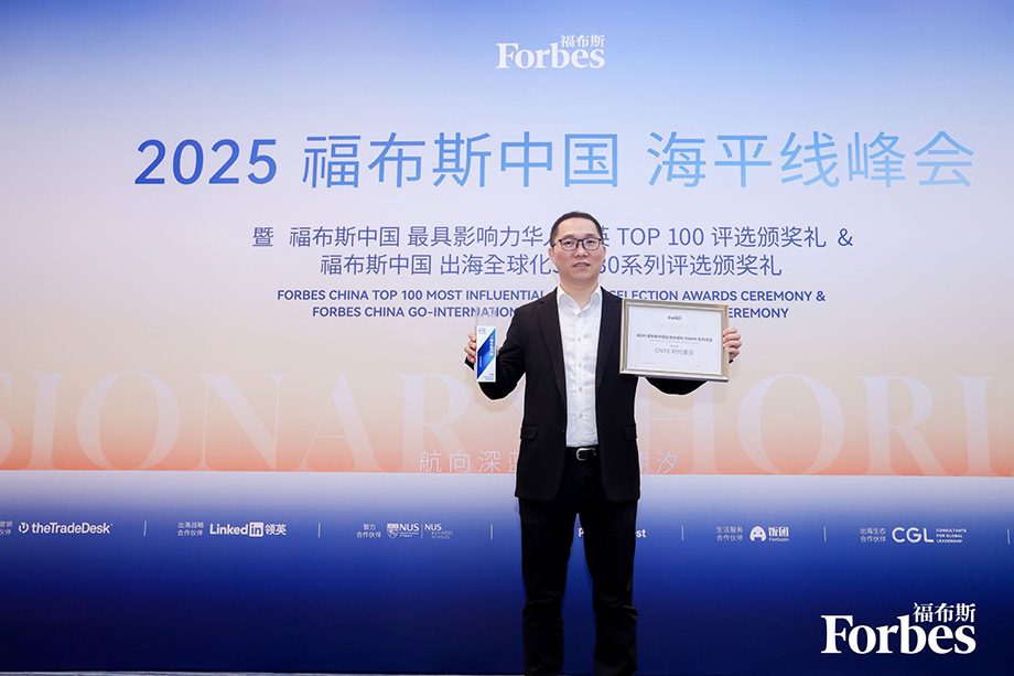
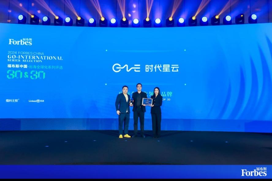
CNTE Honored as 2025 Forbes China Leading Global Brand
Jul 06, 2026 -

CNTE & YOU.ON Partner to Expand Storage Markets
May 19, 2025 -

CNTE Unveils Energy Storage Lineup at Solartech 2025
May 19, 2025 -
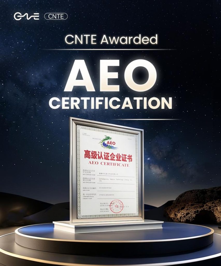
CNTE awarded AEO certification
Jul 06, 2026 -
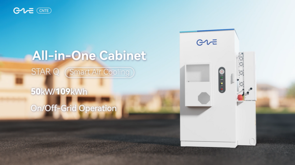
CNTE New Product Launch STAR Q
Jan 15, 2025 -
CNTE Named to Forbes China 2024 Top 30 Go-International Brands
Jul 06, 2026