8 Technical Benchmarks for a Large Battery Storage Container in Utility-Scale Microgrids
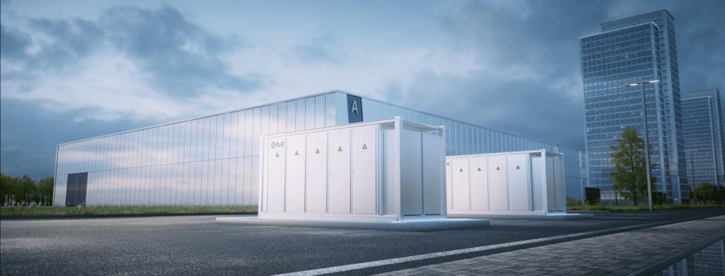
The transition toward a carbon-neutral power grid has necessitated the rapid deployment of high-density energy storage assets. Among the most effective solutions is the large battery storage container, a modular, turnkey system designed to provide multi-megawatt capacity in a standardized footprint. These systems are no longer just backup power sources; they serve as sophisticated grid-stabilization tools capable of performing millisecond-level frequency regulation and large-scale energy shifting. For B2B stakeholders and utility operators, understanding the engineering nuances of these containers is paramount to ensuring project bankability and operational safety.
Modern energy infrastructure providers, such as CNTE (Contemporary Nebula Technology Energy Co., Ltd.), have pioneered the integration of advanced battery management and thermal control within these containerized units. By housing the entire energy ecosystem—including cells, protection systems, and environmental controls—within a ruggedized enclosure, developers can significantly reduce on-site installation time and complexity.
1. The Shift to 1500V DC Bus Architecture
A significant trend in the design of a large battery storage container is the migration from 1000V to 1500V DC systems. This increase in voltage offers several technical advantages for utility-scale projects:
- Reduced Balance of System (BOS) Costs: Higher voltage allows for longer strings and fewer components, which reduces the amount of cabling and the number of combiners needed.
- Higher Energy Density: By increasing the voltage, manufacturers can pack more energy into the same physical footprint, maximizing the utility of a 20-foot or 40-foot container.
- Improved Efficiency: Higher voltage systems generally experience lower resistive losses during power conversion, leading to a higher round-trip efficiency (RTE).
2. Advanced Thermal Management: The Case for Liquid Cooling
Thermal stability is the most decisive factor in battery longevity and safety. In a large battery storage container, thousands of cells operate in close proximity, generating significant heat during high-C-rate discharge cycles. Traditional air-cooling systems often struggle with “hot spots,” where certain modules age faster than others due to uneven airflow.
Liquid cooling has emerged as the industry standard for high-performance systems. By circulating a coolant (typically a water-glycol mixture) through cold plates integrated into the battery racks, heat is removed much more efficiently than with air. This technology allows for cell temperature variance to be kept within a narrow 3°C window. Such precision prevents accelerated chemical degradation and ensures that the State of Health (SoH) remains consistent across the entire system, preserving the asset’s value for its 15-year lifecycle.
3. Lithium Iron Phosphate (LFP) vs. NMC for Industrial Safety
While Nickel Manganese Cobalt (NMC) batteries offer high energy density, the large battery storage container market has moved decisively toward Lithium Iron Phosphate (LFP) chemistry. The primary reason is thermal stability. LFP cells have a much higher thermal runaway threshold and do not release oxygen during a failure, which significantly reduces the risk of fire propagation.
Furthermore, LFP provides a superior cycle life, often reaching 6,000 to 10,000 cycles at 80% Depth of Discharge (DoD). This makes them economically ideal for “heavy cycling” applications such as peak shaving and frequency response, where the battery may be called upon several times per day. CNTE (Contemporary Nebula Technology Energy Co., Ltd.) focuses on LFP-based solutions to provide the highest safety margins for industrial and commercial users.
4. Multi-Layer Battery Management Systems (BMS)
Managing a megawatt-scale battery requires a hierarchical BMS architecture. In a typical containerized setup, the BMS is divided into three levels:
- Slave BMS (BMU): Monitors individual cell voltages and temperatures within a module.
- Master BMS (BCU): Manages a single string of modules, overseeing State of Charge (SoC) balancing and protection logic.
- Central BMS (System Level): Coordinates multiple strings and interfaces with the Power Conversion System (PCS) and the Energy Management System (EMS).
This multi-tier approach ensures that any anomaly—such as an overvoltage or an insulation fault—is isolated immediately without shutting down the entire container, thus maintaining grid uptime.
5. Fire Suppression and Safety Compliance
Safety is the primary industry pain point. A large battery storage container must adhere to rigorous international standards like UL 9540 and NFPA 855. Modern safety protocols involve a “defense-in-depth” strategy:
- Detection: Gas sensors detect “off-gassing” (the release of electrolytes) long before a thermal event occurs.
- Ventilation: Explosion-relief panels and high-speed exhaust fans prevent the buildup of flammable gases.
- Suppression: Integrated fire suppression systems, using clean agents like Novec 1230 or specialized aerosol-based extinguishers, are designed to neutralize fire at the module level.
6. Application Scenarios: Beyond Simple Storage
The versatility of a large battery storage container allows it to address diverse operational challenges across the energy sector:
Grid-Scale Frequency Regulation
Renewable energy sources like wind and solar are intermittent. Containerized storage can inject or absorb power in milliseconds to maintain grid frequency at 50Hz or 60Hz. This ancillary service is highly profitable in mature energy markets.
Black Start Capabilities
In the event of a total grid failure, these containers can provide the initial power needed to “restart” the grid or local power plants without relying on the external transmission network. This is a paramount feature for hospital complexes and industrial parks.
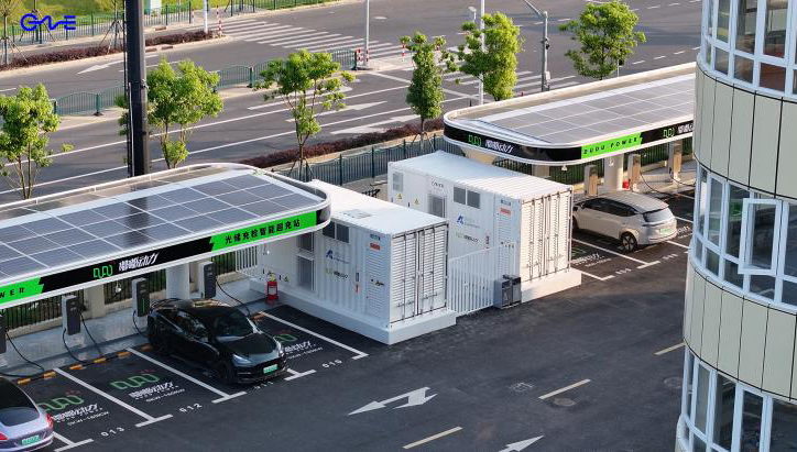
Renewable Energy Firming
By pairing a large battery storage container with a solar farm, operators can “smooth” the output curve. Instead of a volatile production profile, the battery stores excess energy during the day and releases it during the evening peak, making solar power a “baseload-like” resource.
7. Overcoming Interconnection and Integration Hurdles
One of the most significant barriers to deploying large-scale storage is grid interconnection. A large battery storage container must be equipped with smart inverters capable of “grid-following” and “grid-forming” operations. Grid-forming inverters allow the storage system to act as a virtual synchronous generator, providing inertia to the grid, which is lost when traditional coal or gas plants are decommissioned.
Integration also involves software compatibility. The container’s SCADA (Supervisory Control and Data Acquisition) system must communicate seamlessly with the utility’s dispatch center via protocols like DNP3 or IEC 61850. CNTE (Contemporary Nebula Technology Energy Co., Ltd.) ensures their systems are fully compliant with these communication standards for global interoperability.
8. Economic Analysis: LCOS and ROI
The Levelized Cost of Storage (LCOS) is the primary metric for evaluating the financial health of a project. LCOS accounts for the initial CAPEX, annual OPEX (maintenance, cooling energy), and the total energy throughput over the system’s life. By utilizing a large battery storage container, companies can reduce site preparation costs and benefit from economies of scale in battery manufacturing. When combined with revenue stacking—using the same battery for both peak shaving and frequency response—the payback period can often be reduced to under six years.
Securing the Future with Containerized Storage
The deployment of a large battery storage container represents a strategic move toward energy independence and grid resilience. As technology continues to evolve, we can expect even higher energy densities and even more integrated digital twin monitoring systems. For industrial enterprises and utility providers, selecting a solution that prioritizes thermal management, LFP safety, and modular scalability is the most effective way to navigate the complexities of the modern energy sector. By investing in high-quality containerized infrastructure, the path to a sustainable and reliable power future becomes a tangible reality.
Frequently Asked Questions (FAQ)
Q1: What is the standard capacity of a 40-foot large battery storage container?
A1: While capacities vary by manufacturer and chemistry, a modern 40-foot LFP-based container typically ranges from 3.4 MWh to over 5 MWh. The capacity depends heavily on the cooling system design and the density of the battery modules used within the racks.
Q2: How long does it take to install a containerized system on-site?
A2: Because these units are pre-assembled and factory-tested, on-site installation is rapid. Once the concrete pad is ready, the container can be placed, wired to the PCS and transformer, and commissioned within 2 to 4 weeks, depending on grid connection approvals.
Q3: Can these containers withstand extreme environmental conditions?
A3: Yes. High-quality storage containers are rated IP54 or IP55 for dust and water protection. They are also designed with C4 or C5 anti-corrosion coatings for coastal environments and include internal HVAC or liquid cooling systems to operate in temperatures ranging from -30°C to +50°C.
Q4: What is the typical degradation rate for a large-scale LFP container?
A4: With proper thermal management and adherence to recommended C-rates, LFP systems typically experience a 1% to 2% annual capacity fade. Most utility-scale contracts include a “capacity maintenance” clause or an augmentation plan to add more batteries after year 7 or 8 to maintain the original rated capacity.
Q5: Are these systems recyclable at the end of their 15-year life?
A5: Yes, LFP batteries are highly recyclable. The lithium, iron, and phosphate, as well as the aluminum and copper in the cabling and housing, can be recovered. Many jurisdictions now mandate “cradle-to-grave” responsibility, and manufacturers are increasingly involved in second-life applications or material recovery programs.
Q6: Does the container include the inverter (PCS)?
A6: It depends on the configuration. Some designs are “all-in-one,” including the batteries and the PCS in a single container. However, for utility-scale projects, it is more common to have separate battery containers and a centralized PCS container to optimize thermal management and simplify maintenance access.
Get in Touch
Recent Posts
-

CNTE at KEY ENERGY 2026: Showcases STAR H-PLUS Outdoor Liquid-Cooled Energy Storage System
Mar 05, 2026 -

CNTE Honored as 2025 Forbes China Leading Global Brand
Nov 12, 2025 -
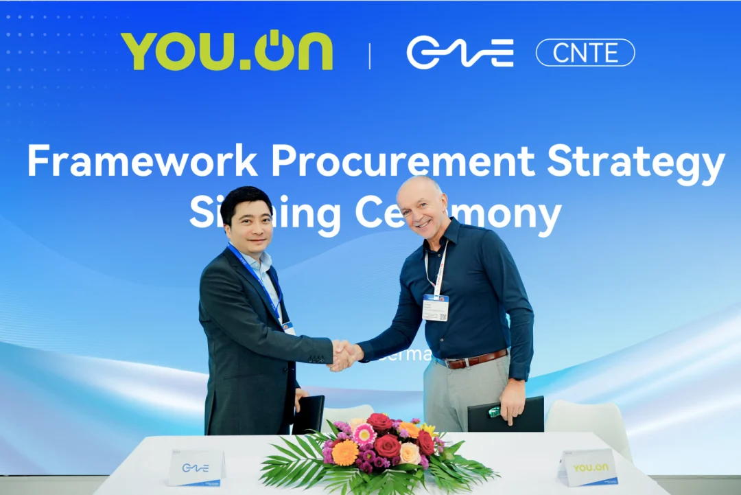
CNTE & YOU.ON Partner to Expand Storage Markets
May 19, 2025 -
CNTE Unveils Energy Storage Lineup at Solartech 2025
May 19, 2025 -
CNTE awarded AEO certification
Mar 14, 2025
Tags
- 1 mw battery storage
- 500 kw battery
- 500 kw battery storage
- 500 kwh battery price
- 500 kwh battery storage
- 50kw solar battery storage
- all in one solar battery
- at home battery
- battery based energy storage
- battery capacity for solar system
- battery electric storage system
- battery energy storage system price
- battery house solar
- battery pack for home solar system
- battery pack house
- battery pack kwh
- battery power storage systems
- battery storage applications
- battery storage device
- battery storage kwh
- battery storage price per kwh
- battery storage suppliers
- battery storage system design
- battery that can power a house
- battery to grid
- bess battery energy
- bess solar system
- better battery renewable energy
- big battery storage
- buy battery storage
- buy solar battery storage
- charging station
- chinese solar batteries
- clean energy storage solutions
- commercial solar power battery storage
- cost of battery storage for solar panels
- cost of solar and battery system
- cost of solar power battery storage
- electric battery storage system
- electrical energy storage exhibition
- energy battery pack
- energy storage battery pack
- energy storage system lithium battery
- energy storage system malaysia
- energy storage system price
- energy storage system solar
- energy tech battery
- ess battery price
- ess battery system
- ess solar battery
- ess solar system
- ev battery for solar storage
- ev battery solar storage
- green energy lithium battery
- high capacity battery for solar panels
- hybrid battery storage
- its technology solar
- kwh battery storage
- large batteries for solar storage
- large battery for solar energy storage
- large battery storage container
- large battery storage systems
- large solar battery storage
- large solar battery storage systems
- large solar storage batteries
- largest commercial battery
- largest solar battery storage
- latest solar batteries
- lithium batteries for off grid solar system
- lithium batteries from china
- lithium battery for off grid solar
- lithium battery for solar system price
- lithium battery home storage
- lithium battery packs for solar panels
- megawatt battery storage
- new battery storage
- off grid solar battery storage
- on grid battery
- on grid battery storage
- optical storage integration
- outdoor energy storage
- outdoor solar battery cabinet
- pcs battery system
- power pack energy
- power storage cells
- price per kwh battery storage
- pv solar panels and battery storage
- q cell battery storage
- smart battery storage
- solar and lithium batteries
- solar batteries inside house
- solar battery battery
- solar battery container
- solar battery kwh
- solar battery module
- solar battery storage cabinet
- solar battery storage capacity
- solar battery storage container
- solar battery storage manufacturers
- solar battery to power house
- solar cell storage
- solar energy battery storage capacity
- solar energy battery storage system
- solar energy lithium battery
- solar energy storage battery price
- solar energy storage system price
- solar energy storage technology
- solar ess system
- solar grid battery
- solar grid battery system
- solar house battery price
- solar installation battery
- solar installation with battery
- solar one batteries
- solar panel battery storage capacity
- solar panel battery storage price
- solar panel energy storage battery
- Solar panel energy storage systems
- solar panel lithium battery storage
- solar panel power storage system
- solar plant battery
- Solar Power Plant Battery
- solar pv and battery storage systems
- solar pv system with battery storage
- solar storage solutions
- solar system and battery storage
- solar with battery system
- solar with lithium battery storage
- standalone energy storage systems
- storage energy battery
- storedge battery