
Utility & C&I Solar Battery Energy Storage System: Advanced Solutions
The global transition toward high-penetration renewable generation has fundamentally altered electrical infrastructure paradigms. Variable photovoltaic output, once managed through spinning reserves and traditional peaker plants, now demands co-located dispatchability. Modern industrial facilities, utility operators, and independent power producers increasingly rely on the advanced solar battery energy storage system as the primary mechanism to decouple generation timing from instantaneous demand curves, stabilize voltage dynamics, and monetize ancillary grid services.
Deploying energy storage alongside commercial and utility-scale solar requires deep domain knowledge across power electronics, electrochemistry, and control topology. Beyond simple time-shifting, these integrated assets must maintain operational availability under aggressive cycling schedules while meeting stringent interconnection standards. Evaluating balance-of-system design, battery degradation dynamics, and system-level thermal dissipation separates commercially viable installations from underperforming capital assets.
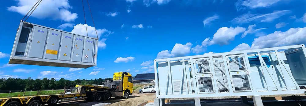
Electrochemical Core: Chemistry Selection and Cell Dynamics
The foundation of any stationary storage deployment rests on electrochemical cell selection. While early deployments experimented with nickel-manganese-cobalt (NMC) formulations due to initial volumetric energy density advantages, the utility and commercial sectors have decisively shifted toward Lithium Iron Phosphate (LFP, LiFePO4). LFP chemistry exhibits superior intrinsic thermal stability, mitigating thermal runaway initiation temperatures up to 270°C compared to approximately 150°C for high-nickel chemistries.
Cell design within the utility landscape focuses heavily on prismatic formats, which offer higher packing efficiencies and mechanically robust structures ideal for heavy outdoor enclosures. Standard commercial capacities have advanced from 280Ah cells toward 306Ah, 314Ah, and 500Ah+ form factors. These larger capacities minimize internal connection counts, reducing system-level failure points across the DC bus.
Electrolyte additives and cathode doping profiles govern degradation over time. Capacity retention hinges on mitigating solid electrolyte interphase (SEI) growth on the graphite anode during both active cycling and static float states. High-performance system integration requires detailed knowledge of depth of discharge (DoD) operational envelopes:
- Cycling Regimes: Limiting continuous operation to 80% or 90% DoD significantly flattens the capacity loss slope compared to 100% cycling, extending asset life beyond 6,000 to 8,000 cycles.
- C-Rate Operational Impact: For utility energy shifting, standard ratings range between 0.25C and 0.5C (4-hour and 2-hour durations), whereas dynamic frequency regulation demands burst capabilities exceeding 1C, driving thermal gradients within the jelly-roll or stacked electrode sheets.
- State-of-Charge (SoC) Resting Windows: Maintaining cells at an elevated resting SoC under ambient heat accelerate calendar degradation. Advanced management algorithms systematically schedule charging cycles to minimize resting hours at peak SoC states.
Power Conversion and Coupling Architecture: AC vs. DC Paradigms
Integrating photovoltaic generation with battery storage introduces fundamental architectural decisions regarding point-of-coupling topology. The choice between DC-coupled and AC-coupled configurations dictates round-trip efficiency (RTE), balance-of-plant costs, and operational flexibility.
DC-Coupled Architecture
In a DC-coupled configuration, the solar array and the battery subsystem feed into a shared DC bus via dedicated DC-DC converters before interfacing with a centralized bidirectional power conversion system (PCS). This architecture reduces conversion steps: renewable electrons charge the battery directly via buck-boost stages, bypassing DC-to-AC and subsequent AC-to-DC rectification losses. Overall round-trip charging efficiency gains typically measure between 1.5% and 3.0%.
DC coupling permits extensive clipping recapture. When solar production exceeds the AC inverter capacity during peak irradiance windows, the surplus DC energy redirects straight into the battery bank rather than undergoing inverter throttling. However, control complexity remains elevated; string-level mismatch and isolation monitoring necessitate specialized protection schemes to prevent fault current propagation between the array and the battery racks.
AC-Coupled Architecture
AC-coupled topologies connect the solar inverter array and the battery system independently at the primary medium-voltage or low-voltage AC bus. Each system operates with autonomous inversion hardware. This separation decouples solar generation hardware from battery control logic, providing distinct advantages for brownfield retrofits and multi-vendor procurement strategies.
Fault isolation is straightforward within AC-coupled designs. A catastrophic failure on the DC side of the battery rack does not impair the photovoltaic plant from exporting power to the off-taker. Furthermore, utility-scale developers frequently favor AC coupling when deploying projects in phases, as storage infrastructure can be installed, commissioned, and validated years after the initial solar farm achieves commercial operation.
Thermal Management Topologies: Liquid Cooling vs. Forced Air
Internal cell temperature homogeneity defines the operational life and safety profile of an industrial solar battery energy storage system. Temperature differentials of more than 3°C to 5°C across a single battery module induce uneven internal resistance profiles, causing cells to charge and discharge at disparate rates. This imbalance forces earlier string curtailment via the battery management system (BMS), degrading the operational nameplate capacity of the entire container.
Historically, forced-air cooling dominated the market, employing high-volume HVAC units directed through complex internal ducting. While mechanically straightforward, forced air exhibits poor heat transfer coefficients. As container energy densities climbed from 2.5 MWh to over 5 MWh per standard 20-foot shipping container envelope, air cooling proved unable to prevent localized hot spots during high-ambient or high C-rate operations without excessive parasitic auxiliary power consumption.
Liquid cooling has become the engineering standard for high-density architectures. Chilled glycol-water mixtures circulate through precision-machined aluminum cold plates positioned in direct contact with cell surfaces. This configuration delivers substantial engineering advantages:
- Thermal Uniformity: Advanced liquid distribution channels maintain inter-cell temperature variances within 2.5°C across the entire container, suppressing divergent aging rates.
- Auxiliary Energy Reduction: The high heat capacity of liquid reduces the continuous auxiliary parasitic load by up to 30% compared to equivalent air-cooled systems, elevating the net plant round-trip efficiency.
- Environmental Enclosure Isolation: Liquid-cooled enclosures eliminate the massive open air intake vents required by HVAC systems, allowing cabinets to achieve IP55 to IP67 ingress protection. This effectively isolates sensitive electronics from coastal salt spray, desert particulate abrasion, and industrial chemical contaminants.
Specialized systems developed by CNTE (Contemporary Nebula Technology Energy Co., Ltd.) leverage advanced liquid-cooling loops combined with multi-sensor monitoring to deliver uniform thermal performance across demanding grid-tied cycles.
BMS, EMS, and Substation SCADA Integration Layers
The operational intelligence of an integrated storage installation spans a three-tier control hierarchy consisting of the Battery Management System (BMS), the Power Conversion System controller (PCS), and the site-level Energy Management System (EMS).
Battery Management System (BMS)
The BMS functions as the mission-critical hardware protection and state-estimation layer. Operating at the cell, module, and rack levels, the BMS executes real-time sampling of cell voltage, current, and multiple temperature points at millisecond intervals. Core calculations include:
- State of Charge (SoC): Calculated via hybrid Extended Kalman Filter (EKF) algorithms combined with coulomb counting to eliminate drift over extended high-throughput periods.
- State of Health (SoH): Evaluated through internal impedance tracking and capacity fade modeling during full discharge cycles.
- Active vs. Passive Balancing: Advanced BMS designs implement active balancing circuits that shuttle charge between adjacent cells, rather than burning off excess power through bleed resistors (passive balancing), maintaining string cohesion without generating local heat loads.
Energy Management System (EMS) and Grid Protocols
The EMS bridges local storage telemetry with the broader grid operator or facility supervisor control and data acquisition (SCADA) system. The EMS processes complex multi-objective optimization algorithms, deciding when to charge from co-located solar, when to draw from the grid, and when to dispatch energy into the wholesale market based on pricing signals, weather forecasts, and transmission capacity limitations.
Deterministic communication protocols are mandatory to execute dynamic grid commands. Field buses rely on high-speed Modbus TCP/IP, DNP3, and IEC 61850. For utility applications, IEC 61850 provides the object-oriented data structures necessary to coordinate instantaneous reactive power support (volt/var) and active power frequency response (watt/frequency) directly with high-voltage utility substation automation systems.
Commercial Value Vectors and Revenue Stacking
Calculating the levelized cost of storage (LCOS) requires balancing upfront capital expenditure (CapEx) against the lifetime throughput and multi-revenue stacking capability of the asset. Modern industrial facilities and utility operators rely on integrated storage systems to tap multiple economic streams simultaneously.
Peak Shaving and Demand Charge Avoidance
Industrial manufacturing hubs face steep utility tariff structures where peak power draw during specific monthly hours dictates a substantial portion of the total electricity bill. High-speed EMS algorithms deploy storage to cap facility imports precisely when manufacturing loads peak, mitigating thousands of dollars in monthly utility capacity penalties.
Energy Arbitrage
Wholesale market pricing volatility creates direct arbitrage opportunities. System operators charge the battery bank during periods of low, zero, or negative wholesale pricing—frequently caused by regional solar overgeneration midday—and discharge the stored energy during evening peak pricing windows when generation assets command premium rates.
Ancillary Services
Due to the near-instantaneous response times of modern bidirectional inverters (sub-100 millisecond response), a solar battery energy storage system provides superior grid-stabilization services compared to conventional thermal generation. Operators monetize:
- Fast Frequency Response (FFR): Rapid injection or absorption of active power to counter sudden system-frequency deviations caused by unexpected generation trips or line faults.
- Spinning and Non-Spinning Reserves: Providing capacity commitments to transmission system operators without continuously running physical combustion turbines at partial, inefficient loads.
- Black Start Capabilities: Utilizing voltage-source inverters to establish a local microgrid reference voltage, enabling downstream utility infrastructure restoration following catastrophic regional blackouts.
Safety Engineering, Failure Containment, and Regulatory Compliance
Safety engineering represents the single most critical gating item for system commissioning and property underwriting. Deploying multi-megawatt-hour electrochemical installations in industrial or suburban settings requires deterministic protection against cascading thermal runaway events.
Modern system architecture follows defense-in-depth principles. Early warning systems identify off-gassing products long before thermal runaway elevates temperatures. Sensors detecting carbon monoxide (CO), hydrogen (H2), and early volatile organic compounds (VOCs) trigger automated electrical isolation and ventilation before lower explosive limit (LEL) concentrations are reached.
Physical barrier design limits cell-to-cell and module-to-module propagation. Inter-cell aerogel insulation sheets and localized fire-resistant phase-change materials inhibit heat transfer between adjacent prismatic cans. Container-level fire suppression typically deploys dual-action protocols: clean-agent gaseous systems (e.g., Novec 1230 or FK-5-1-12) to extinguish immediate flame development, integrated alongside dry-pipe water deluge systems designed to provide sustained boundary cooling to prevent reignition.
System designers must strictly align with global testing standards:
- UL 9540: System-level safety certification assessing the combined electrical, mechanical, and fire protection integration of the inverter and battery enclosures.
- UL 9540A: Standardized test method for evaluating thermal runaway fire propagation behavior in battery energy storage systems at the cell, module, unit, and installation level.
- NFPA 855: Standard for the Installation of Stationary
Energy Storage Systems, governing mandatory container separation distances,
water supply duration, and deflagration venting capacities.
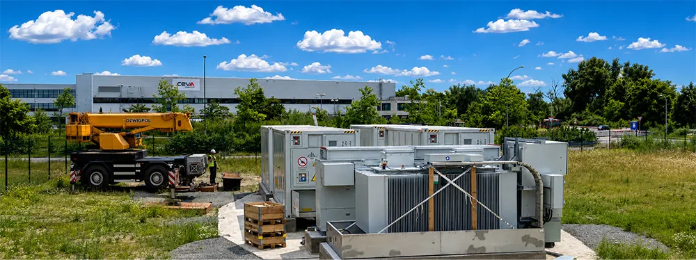
Full-Scenario Deployment Engineering
Deploying storage across diverse environments—from high-altitude, cold-climate solar plants to hyper-arid desert conditions—imposes unique balance-of-plant requirements. In desert installations, solar irradiance is abundant, but ambient operational temperatures frequently exceed 45°C. System cooling circuits must be engineered with redundant pumping stations and high-ambient condensers to maintain efficiency while mitigating accelerated electrolyte degradation.
In islanded or weak-grid mining sites, the storage asset frequently functions in grid-forming mode rather than grid-following mode. Grid-following systems require an established external voltage and frequency reference from the grid to synchronize and export power. Grid-forming inverters, by contrast, act as an ideal voltage source, synthesizing the primary AC waveform and supplying instantaneous synthetic inertia via localized control loops. This allows 100% renewable penetration scenarios without reliance on diesel generation foundations.
Leading hardware architectures engineered by CNTE (Contemporary Nebula Technology Energy Co., Ltd.) address these full-scenario operational demands through modular containerized platforms, ensuring consistent balance-of-plant stability whether deployed for commercial peak shaving, industrial process continuity, or massive utility stabilization.
Procurement and Technical Evaluation Criteria
Industrial stakeholders evaluating an advanced solar battery energy storage system must look beyond initial nameplate CapEx metrics. A rigorous technical due-diligence framework evaluates holistic operational attributes that dictate the lifetime Total Cost of Ownership (TCO):
- Guaranteed Usable Energy vs. Nameplate Energy: Assessing energy availability across the end-of-life (EoL) threshold, accounting for internal DC system losses and auxiliary parasitics.
- Degradation Curves and Warranty Conditions: Scrutinizing the relationship between allowable annual equivalent throughput (MWh cycled), average operating temperatures, and battery warranty backing. High-tier suppliers specify performance warranties tied directly to clear operating models rather than vague operating restrictions.
- Supply Chain Transparency and ESG Verification: Sourcing traceability for core active materials (lithium, iron, phosphate) to ensure compliance with emerging international supply chain mandates.
- Commissioning Timeline and Field Support: Modular, pre-assembled, factory-tested skids drastically reduce civil work and field integration hours, preventing costly delays during high-voltage utility interconnection inspections.
Frequently Asked Questions
What is the typical operational lifespan of a commercial solar battery energy storage system?
Modern stationary energy storage platforms utilizing high-quality LFP chemistry typically deliver an operational lifespan between 10 and 15 years, corresponding to 6,000 to 10,000 equivalent full cycles under standardized operating conditions (e.g., 0.5C/0.5C cycles at 25°C with 80% to 90% DoD). End-of-life is typically defined when the system drops to 70% of its initial rated capacity. Extending asset longevity depends directly on active thermal management and avoiding prolonged storage at extreme states of charge.
How does liquid cooling compare to HVAC air cooling in utility storage environments?
Liquid cooling provides significantly higher thermal transfer rates, allowing the system to keep inter-cell temperature variations within 2.5°C across high-density battery racks. Air cooling systems frequently experience internal temperature gradients exceeding 5°C to 8°C during peak summer or high-rate cycling, driving uneven cell aging and premature system capacity loss. Liquid cooling also reduces auxiliary power consumption by up to 30% and permits fully sealed enclosures (IP55/IP67) that prevent external dirt and moisture ingress.
What is the difference between grid-following and grid-forming storage inverters?
Grid-following inverters measure the external voltage angle of the electrical grid via phase-locked loops (PLL) and inject current synchronized to that established waveform. If the grid disconnects, grid-following systems must shut down immediately to prevent unsafe islanding. Grid-forming inverters utilize sophisticated control algorithms to establish their own internal voltage and frequency reference. This allows them to supply synthetic inertia, support black-start operations, and stabilize weak grids or off-grid industrial microgrids with zero baseline thermal generation.
How do project developers monetize energy storage through revenue stacking?
Revenue stacking involves orchestrating the dispatch of the storage system across multiple distinct economic opportunities throughout the day. A commercial system may deploy energy to shave industrial facility peak demand charges in the afternoon, participate in high-value grid frequency regulation programs when demand charges are low, and perform energy arbitrage by charging from midday solar generation and discharging during high-rate evening wholesale windows.
Which fire safety certifications are mandatory before installing battery systems near commercial facilities?
Municipal authorities and industrial insurers universally look for UL 9540 system safety certification, which verifies that the power electronics, battery racks, software controls, and enclosure subsystems interact safely. Additionally, detailed UL 9540A testing data must be provided to evaluate cell-level, module-level, and unit-level thermal runaway behavior. Installations must also comply with NFPA 855 standards governing physical clearance separations, fire suppression agent requirements, and emergency ventilation strategies.
Initiate Your Storage Project Consultation
Deploying a utility or industrial energy asset demands precision engineering, detailed economic modeling, and compliance validation. Transitioning from feasibility planning to procurement requires clear technical specifications tailored to your localized grid connection, operational profiles, and commercial monetization strategy.
Submit your site-specific parameters, interconnection requirements, and load profiles to our engineering integration team to receive a comprehensive technical proposal, single-line architecture design, and lifetime levelized cost analysis tailored to your operational goals.
Get in Touch
Recent Posts
-
CNTE Included in BloombergNEF's Q4 2026 Tier 1 Energy Storage Manufacturers
Nov 03, 2026 -
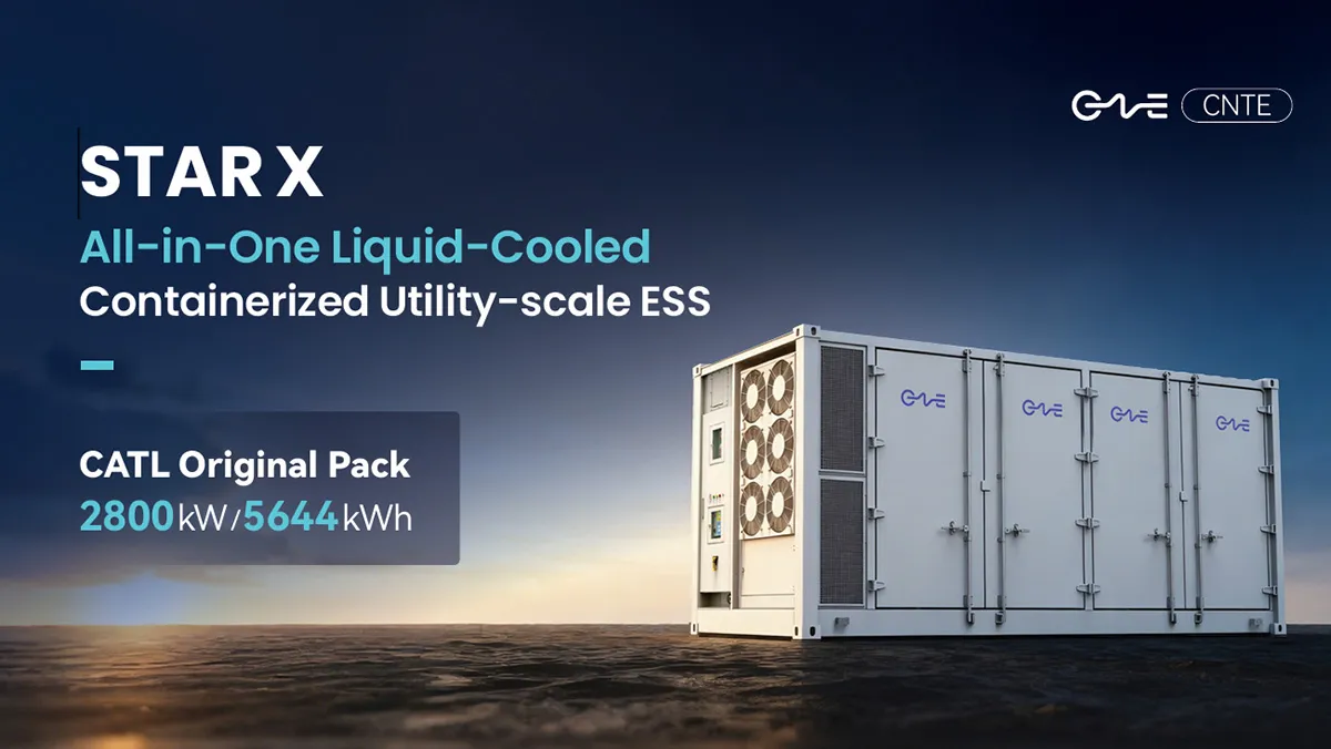
CNTE Launches STAR X Liquid-Cooled DC/AC Integrated Energy Storage System at Intersolar Europe 2026
Jul 06, 2026 -
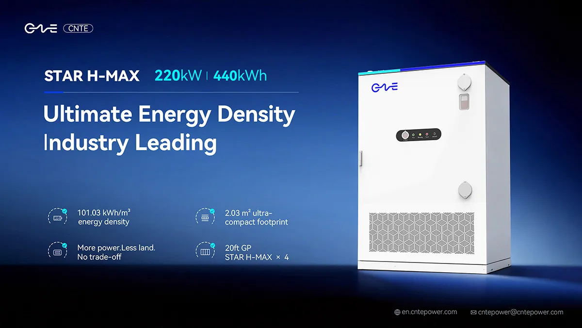
CNTE Unveils New STAR H-MAX Liquid-Cooled C&I ESS at Intersolar Europe 2026
Jun 23, 2026 -
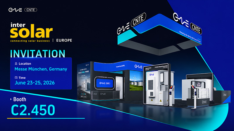
CNTE to Participate in Intersolar Europe 2026
May 20, 2026 -
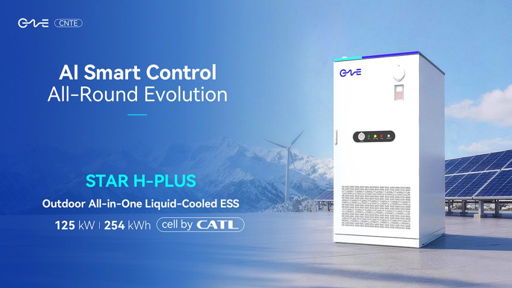
CNTE at KEY ENERGY 2026: Showcases STAR H-PLUS Outdoor Liquid-Cooled Energy Storage System
Mar 05, 2026 -

CNTE Honored as 2025 Forbes China Leading Global Brand
Jul 06, 2026 -
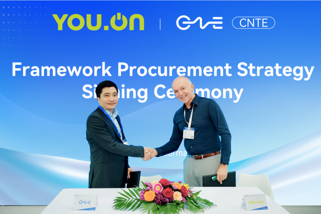
CNTE & YOU.ON Partner to Expand Storage Markets
May 19, 2025 -

CNTE Unveils Energy Storage Lineup at Solartech 2025
May 19, 2025 -
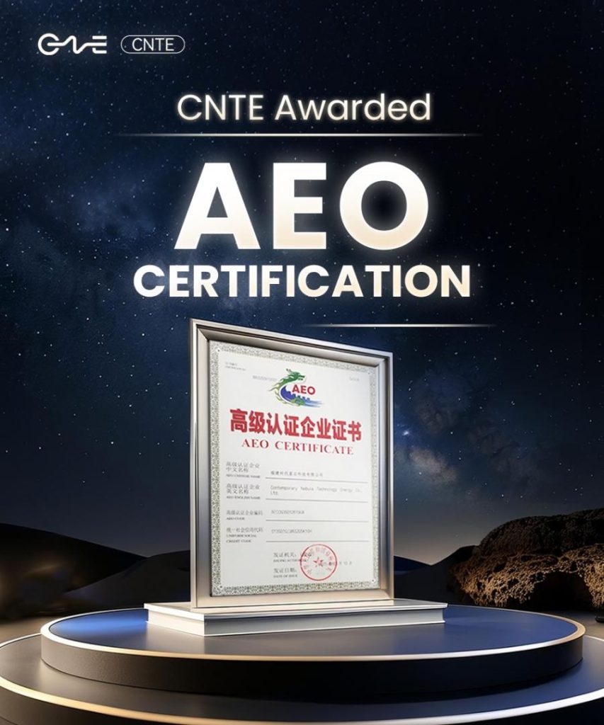
CNTE awarded AEO certification
Jul 06, 2026 -
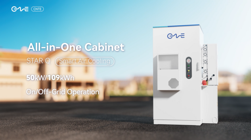
CNTE New Product Launch STAR Q
Jan 15, 2025
