
Comprehensive Guide to BESS Battery System Infrastructure for C&I and Utility-Scale Deploymen
Global electrical networks are undergoing structural shifts toward decentralized, intermittent renewable generation. This pivot necessitates robust, fast-responding infrastructure capable of resolving the mismatch between energy supply curves and instantaneous load demands. The utility-scale and commercial bess battery system serves as the foundational infrastructure bridging this operational gap. Far from being a mere collection of electrochemical cells, a modern energy storage asset is a tightly integrated ecosystem combining electrochemistry, power conversion electronics, dynamic thermal control systems, and microsecond-level software orchestration. Maximizing asset yield requires an exhaustive understanding of its sub-systems, operational physics, and real-time interaction with complex power grids.
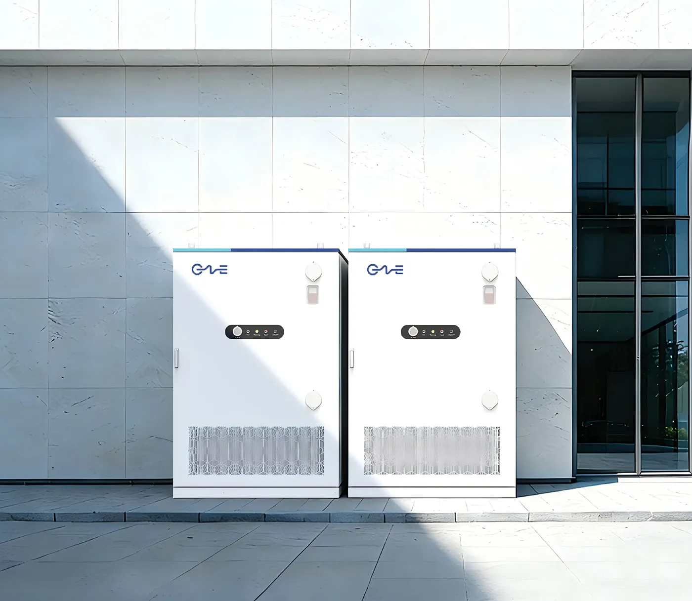
Electrochemical Core and Mechanical Assembly Architecture
At the center of energy density and lifetime throughput is electrochemical selection. While various chemistries occupy specialized niches, lithium iron phosphate (LiFePO4 or LFP) has emerged as the definitive standard for stationary grid assets. LFP offers intrinsic thermal stability, long operational lifetimes exceeding 6,000 to 10,000 cycles under controlled operating bands, and a supply chain free from cobalt and nickel constraints.
The transition from bare materials to a field-deployable bess battery system demands rigorous multi-stage physical integration. Individual prismatic cells, typically rated between 280Ah and 314Ah, are connected in series and parallel topologies to form distinct modules. Advanced structural designs increasingly bypass intermediate modular housing through Cell-to-Pack (CTP) or Cell-to-Container arrangements. This paradigm elevates volumetric energy density, reduces structural weight, and minimizes internal electrical connection points, substantially curtailing inter-cell resistance variations that otherwise accelerate pack-level unbalance.
Higher packing density amplifies the requirements on the structural chassis. Mechanical enclosures must withstand external mechanical stress, dynamic transport loads, seismic events according to IEEE 693 standards, and environmental ingress. Industrial deployments utilize outdoor-rated enclosures featuring minimum IP55 or NEMA 3R ratings, fortified with anti-corrosion coatings rated for C4 or C5-M industrial environments.
Power Conversion, System Topology, and Grid Synchronization
The Power Conversion System (PCS) operates as the bidirectional energy corridor between the DC electrochemical array and the AC distribution or transmission network. System topology choices at this junction govern system efficiency, fault handling, and dispatch agility.
Centralized versus Distributed Inverter Topologies
System designers face an architectural trade-off between centralized and string-based power electronics. Centralized topologies route massive DC arrays to a singular, high-capacity inverter block, typically ranging from 1 MW to 3.45 MW. This methodology provides lower initial hardware capital expenditure, streamlined maintenance regimes at a singular physical location, and established utility-scale grid interconnect paradigms.
Conversely, distributed architectures connect smaller string inverters to discrete subsets of the battery racks. By isolating rack groups through individual Maximum Power Point Tracking (MPPT) loops or discrete DC bus inputs, distributed designs virtually eliminate cross-string circulating currents and suppress capacity mismatch losses. If an inverter channel fails, the balance of the plant maintains dispatch capabilities, protecting operational revenue metrics.
Bus Architecture: 1000V versus 1500V Systems
Modern megawatt-scale engineering has standardized on 1500V DC topologies, shifting away from legacy 1000V baselines. Elevating DC voltage limits current throughput for an equivalent power rating, yielding immediate technical dividends:
- Reduction in balance-of-system (BoS) copper conductor cross-sectional areas.
- Measurable decrease in line impedance and I²R resistive thermal losses.
- Enhanced integration efficiency through direct alignment with high-power industrial grid-forming inverters.
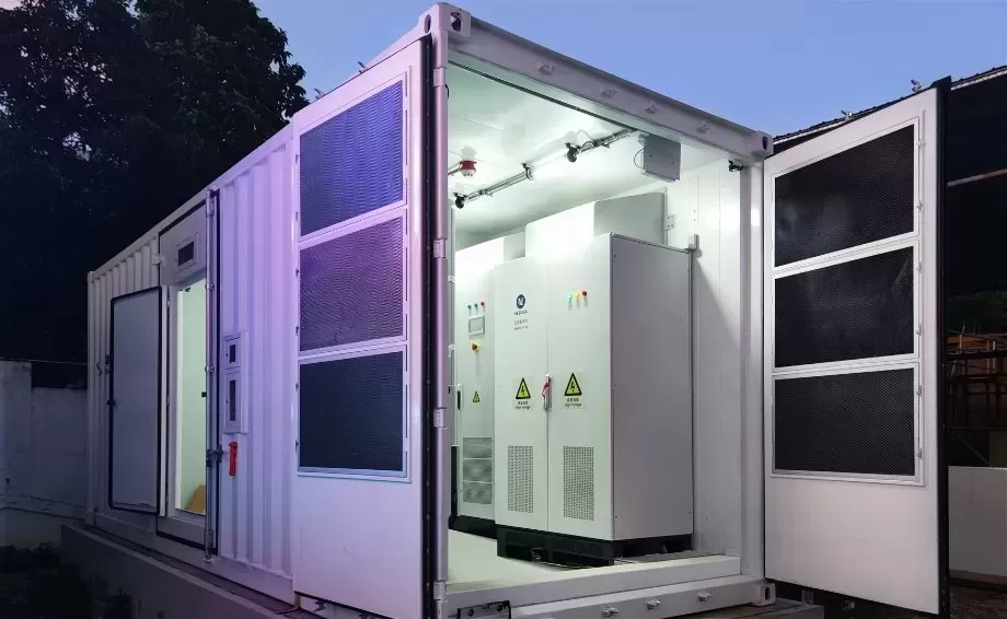
- Optimized container footprint, unlocking upwards of 3.7 MWh to 5 MWh within a standard 20-foot enclosure footprint.
Thermal Equilibrium: Liquid Cooling versus Air Exchange
Cell longevity is inextricably tied to thermal operating windows. Accelerating degradation mechanisms—such as solid electrolyte interphase (SEI) layer growth, lithium plating, and active material dissolution—are direct outcomes of elevated temperatures or wide thermal gradients across a rack. Operating a pack at sustained internal temperatures above 35°C cuts its anticipated service calendar life dramatically, while spatial thermal gradients exceeding 3°C between adjacent series cells lead to uneven impedance trajectories and premature string retirement.
Thermal management within a bess battery system directly dictates asset profitability through both parasitic load footprints and degradation curves. Traditional forced-air HVAC systems rely on convection through ducting across dense cell matrices. While simple in design, air provides poor volumetric heat capacity, resulting in wide delta-T variations from the front to the rear of the enclosure, alongside high parasitic auxiliary consumption.
Next-generation architectures implement closed-loop liquid cooling systems. Coolant plates, machined from precision aluminum alloys and featuring engineered micro-channels, interface directly with cell surfaces via specialized thermal interface materials (TIM). Ethylene-glycol water mixtures are circulated at controlled flow rates dictated by real-time cell telemetry. Liquid systems achieve thermal equilibrium with intra-rack temperature gradients held strictly below 2.5°C, while slashing auxiliary energy consumption by up to 30% relative to forced-air counterparts. The resulting thermal uniformity maintains equivalent state-of-charge tracking across all strings and dampens cell wear over decades of cyclic dispatch.
Multi-Tier Management Architecture: BMS and EMS Integration
Digital control systems govern the envelope of safety, state determination, and financial monetization for energy storage installations. This computational network is stratified across distinct hierarchical tiers.
Battery Management System (BMS)
The BMS functions as the primary operational watchdog, partitioned across three structural tiers:
- Battery Module Unit (BMU): Microcontrollers deployed directly onto module backplanes to sample cell voltages and thermistor points at millisecond frequencies, handling localized active or passive cell balancing.
- Battery Cluster Unit (BCU): Rack-level computational nodes compiling string metrics, managing DC contactors, calculating real-time short-circuit and over-current trip limits, and projecting string-level state of charge (SoC) and state of health (SoH).
- Battery Array Management System (BAMS): The macro-level aggregation layer consolidating cluster inputs across the complete DC field, presenting unified system limits to the power conversion layer.
Energy Management System (EMS) and SCADA
Above the BMS sits the site-level Energy Management System (EMS). The EMS is the decision engine responsible for dispatch optimization, interacting with supervisory control and data acquisition (SCADA) networks, independent system operators (ISOs), and on-site industrial loads. Operating with response latencies under 20 milliseconds, the EMS shifts effortlessly between differing operating modes: frequency response, capacity firming, load peak smoothing, and wholesale energy arbitrage.
Advanced implementations apply Kalman filtering, neural networks, and physical degradation models within the EMS software layer. This allows the system to calculate the true marginal degradation cost of executing a dispatch event against spot wholesale electricity pricing, ensuring the asset never dispatches power when market remuneration falls below long-term cell replacement costs.
Industrial and Utility Applications of the BESS Battery System
Implementing an industrial bess battery system unlocks dynamic value stacks across diverse nodes of the electrical transmission and distribution ecosystem.
Utility-Scale Grid Support Services
At the grid operator scale, electrochemical storage provides ancillary services historically provided by rotating thermal mass. When a large transmission line trips, energy storage responds within milliseconds to inject active power, arresting frequency decay. Frequency containment reserves (FCR), synthetic inertia, and black start capabilities represent foundational applications where sub-second electrochemical responses outmatch gas peaker thermal units, decreasing grid balancing costs while reinforcing network security.
Commercial and Industrial Peak Shaving and Resiliency
Manufacturing facilities, data centers, and heavy processing plants encounter escalating electrical demand charges levied on their maximum half-hour power draws. Energy storage systems detect when facility loads approach peak thresholds, instantly discharging to suppress grid draw beneath the billing threshold. Concurrently, these systems supply power continuity during localized distribution dropouts, operating as uninterruptible industrial power nodes that decouple critical operational processes from broader grid volatility.
Renewable Co-Location: Solar-Plus-Storage and Wind Firming
Pairing utility photovoltaics or wind turbines with high-density storage resolves resource intermittency. The storage system absorbs generation during periods of midday solar overproduction or excessive nighttime wind output, mitigating economic losses associated with operator-mandated grid curtailment. Stored power is systematically dispatched during peak demand hours, transforming unstable variable renewable resources into fully dispatchable, base-load generation assets.
Industrial System Reliability and Manufacturing Protocols
Engineering operational longevity into an electrochemical system requires precision manufacturing, multi-stage physical fail-safes, and clean production lines. Engineering frameworks developed by CNTE (Contemporary Nebula Technology Energy Co., Ltd.) demonstrate how a bess battery system achieves high availability through comprehensive system integration. Deploying storage at scale requires transitioning away from fragmented field construction toward prefabricated, factory-tested modular containers.
Modern system assembly requires pristine dry-room environments where relative humidity is strictly maintained below 1% during cell exposure phases to avoid micro-scale moisture contamination. The integration architecture deployed by CNTE emphasizes modular scalability, using rigorous component screening to ensure that cell batches possess near-identical internal impedance and capacity metrics before pack assembly. This rigorous upstream qualification prevents premature string divergence, reducing future balancing overheads and maximizing the usable energy envelope over the system lifespan.
Comparative Architecture Analysis
Selecting the structural design configuration for an industrial deployment requires matching application duty cycles with appropriate technical foundations:
| System Parameter | Conventional Air-Cooled 1000V System | Advanced Liquid-Cooled 1500V System |
|---|---|---|
| Volumetric Energy Density | Low to Moderate (< 2.5 MWh per 20ft enclosure) | Ultra-High (> 3.7 MWh to 5.0 MWh per 20ft enclosure) |
| Average Operating Cell Temp Delta | 4°C to 8°C across the system | Strictly ≤ 2.5°C across all modules |
| Auxiliary Power Overhead | High (Substantial continuous HVAC loads) | Low (Dynamic, variable-frequency pump loops) |
| Balance of System (BoS) Footprint | Substantial cabling, multiple combiner boxes | Streamlined DC cabling, optimized container footprints |
| Projected Degradation Rates | Elevated due to localized hotspot persistence | Minimized via steady, uniform thermal dissipation |
Levelized Cost of Storage (LCOS) and Lifecycle Financial Dynamics
Asset viability hinges upon optimizing the Levelized Cost of Storage (LCOS), an all-inclusive financial framework that quantifies the discounted lifecycle cost of the asset per unit of cumulative energy discharged. Calculating LCOS demands a full-spectrum evaluation of operational metrics:
LCOS = (Initial CAPEX + Present Value of OPEX + Decommissioning Cost) /
Total Cumulative Energy Discharged (MWh)
Multiple dynamic parameters dictate the final denominator of this equation:
- Round-Trip Efficiency (RTE): The percentage of energy injected into the storage asset that is successfully returned to the grid. While raw cells may boast 95% efficiency, parasitic auxiliary draw (cooling pumps, controllers, transformation losses) lowers system-level AC-to-AC RTE. Maintaining system RTE above 86-88% directly preserves operational operating margins.
- Depth of Discharge (DoD) Protocols: System algorithms must actively calibrate cycling intensity. Cycling an LFP string to 100% DoD accelerates stress on internal crystal structures; restricting operational sweeps to 80% or 90% DoD can dramatically expand cumulative lifetime cycle counts, yielding greater lifetime energy throughput before capacity reaches end-of-life thresholds (typically 70% of initial rating).
- Scheduled Augmentation Profiles: Electrochemical capacity
fades over time. System planners must choose between upfront overbuild
(installing extra initial capacity that lies underutilized for years) or
scheduled augmentation (adding modular DC capacity at Year 5 or Year 10 to
restore baseline capacity). Modular layouts simplify field augmentation,
enabling asset owners to exploit continuing historical reductions in battery
cell costs.
Frequently Asked Questions
What is the typical lifecycle and degradation timeline of a modern energy storage asset?
Standard Tier-1 lithium iron phosphate systems achieve between 6,000 and 10,000 full equivalent cycles at 80% Depth of Discharge (DoD) under nominal thermal control parameters before depleting to 70% of original rated capacity. In standard daily cycling profiles, this equates to a design life of 15 to 20 years. Operational life is governed by operating temperatures, high C-rate cycling frequency, and the precision of the battery management platform's balance systems.
How does 1500V DC topology improve operational economics over 1000V designs?
A 1500V system lowers operating current for a given power demand by approximately 33% relative to a 1000V baseline. Lower current directly translates to reduced cross-sectional requirements for power cabling and decreased copper expenses. Furthermore, it halves the total number of balance-of-system combiners and reduces resistive thermal energy losses throughout the electrical run, boosting aggregate round-trip efficiency while freeing internal space for active storage media.
Why is liquid cooling preferred over traditional HVAC systems in dense energy containers?
Liquid coolants feature heat capacities several hundred times higher than air by volume. Direct thermal exchange via dedicated cold plates lowers inter-cell and inter-rack temperature variations to below 2.5°C, compared to swings of 6°C or more in forced-air systems. Limiting hot spots prevents uneven degradation, ensures uniform impedance profiles across the array, and reduces parasitic energy draw by eliminating energy-intensive HVAC compressor cycling.
What core protocols dictate communication between the BMS, EMS, and balance of plant?
Industrial integration leverages multi-tiered deterministic industrial protocols. Modbus TCP/IP and CAN bus remain the baseline communication layers for intra-rack cell and cluster monitoring between BMUs and BCUs. At the microgrid, substation, and macro-grid layer, modern Energy Management Systems interface through IEC 61850, IEC 60870-5-104, or DNP3 to facilitate seamless telemetry transfer, real-time command dispatch, and centralized grid utility synchronization.
Can modular energy storage systems be expanded or augmented after initial commissioning?
Yes. Systems built with modular DC bus architectures and individual string conversion stages support phased augmentation. Because battery cells exhibit lower internal resistance when new, mixing new racks directly into legacy DC arrays can cause cross-string current circulation. Modern engineering designs mitigate this issue through dedicated DC-DC optimizers or isolated string inverters, allowing new storage racks to be integrated seamlessly into operational infrastructure without disturbing older strings.
Procurement and Technical Consultation
Executing a utility or commercial energy storage deployment requires careful planning, balance-of-plant design, and rigorous adherence to performance targets. Selecting the optimal layout, system voltages, and thermal management architecture directly dictates operational reliability and levelized cost of energy for decades to come.
Consulting with CNTE (Contemporary Nebula Technology Energy Co., Ltd.) provides utility planners with access to integrated, high-density electrochemical systems, pre-engineered enclosures, and end-to-end grid interconnect optimization. Submit technical project specifications to our industrial engineering and procurement group to initiate an exhaustive system sizing, dispatch profiling, and system architecture assessment tailored precisely to your operational requirements.
Get in Touch
Recent Posts
-
CNTE Included in BloombergNEF's Q4 2026 Tier 1 Energy Storage Manufacturers
Nov 03, 2026 -
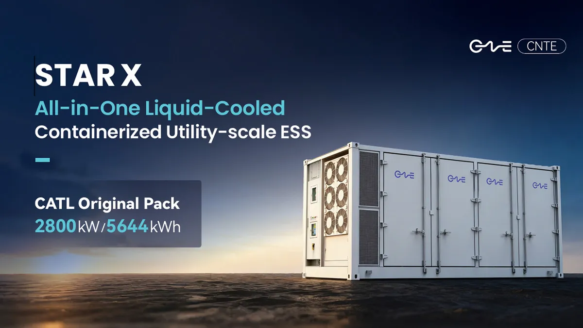
CNTE Launches STAR X Liquid-Cooled DC/AC Integrated Energy Storage System at Intersolar Europe 2026
Jul 06, 2026 -
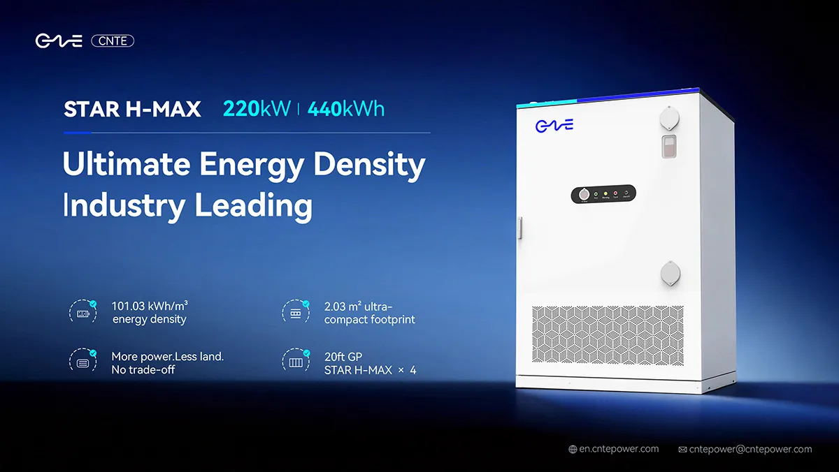
CNTE Unveils New STAR H-MAX Liquid-Cooled C&I ESS at Intersolar Europe 2026
Jun 23, 2026 -
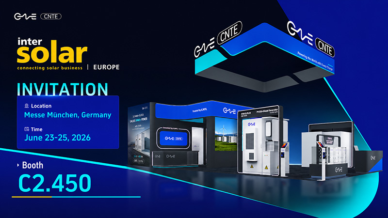
CNTE to Participate in Intersolar Europe 2026
May 20, 2026 -
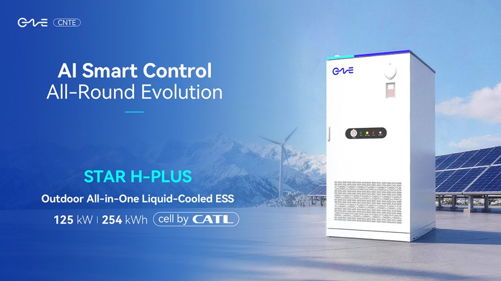
CNTE at KEY ENERGY 2026: Showcases STAR H-PLUS Outdoor Liquid-Cooled Energy Storage System
Mar 05, 2026 -

CNTE Honored as 2025 Forbes China Leading Global Brand
Jul 06, 2026 -

CNTE & YOU.ON Partner to Expand Storage Markets
May 19, 2025 -

CNTE Unveils Energy Storage Lineup at Solartech 2025
May 19, 2025 -

CNTE awarded AEO certification
Jul 06, 2026 -
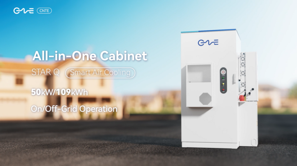
CNTE New Product Launch STAR Q
Jan 15, 2025
