
Utility & C&I BESS in Solar: Engineering Guide to Next-Gen Energy Storage
The global transition toward high-penetration renewable energy has exposed the operational limitations of standalone photovoltaic (PV) generation. Solar generation profiles naturally decouple from regional load profiles, creating systemic grid imbalances characterized by mid-day overgeneration and steep evening net-load ramps. Within this context, the integration of bess in solar has shifted from a margin-enhancing luxury to a fundamental engineering requirement. Contemporary utility-scale and commercial projects demand dispatchable, controllable, and resilient capacity that can withstand aggressive interconnect standards while maximizing asset revenue throughout a multi-decade operational lifespan.
Modern battery energy storage systems coupled with solar arrays mitigate the physical limitations of intermittent generation. By converting non-synchronous, intermittent solar energy into dynamic, dispatchable power blocks, these hybrid assets fulfill complex operational criteria: mitigating high interconnection upgrade expenditures, capturing negative power pricing arbitrage, and supplying synthetic inertia to weakening grid networks. Achieving these operational goals requires an exhaustive evaluation of electrical topologies, electrochemical profiles, balance of plant (BoP) configurations, and long-term asset augmentation schedules.
Grid Interconnection Bottlenecks and Curtailment Mechanics
Photovoltaic generation capacity frequently outpaces local distribution and transmission capacity. Utilities increasingly impose dynamic export limitations or schedule aggressive curtailment periods to prevent transmission feeder thermal overloads and uncontrolled voltage excursions. These operational limits undermine the underlying pro forma models of standalone solar assets by stranding generated kilowatt-hours behind the point of common coupling (PCC).
Curtailment manifests primarily in two operational modes: economic curtailment, where wholesale clearing prices plunge into negative values due to regional oversupply, and physical curtailment, where system operators command power output cuts to maintain transmission line thermal ratings. Energy storage rectifies both challenges. When the generation curve breaches export limits, the excess direct current (DC) or alternating current (AC) is redirected into energy storage cells rather than throttled by inverter power point tracking (MPPT) clipping.
Integrating utility-scale energy storage also circumvents expensive grid interconnection queue constraints. Asset developers can oversize the PV generation field relative to the point of interconnect (POI) nameplate capacity—a design concept known as a high DC-to-AC capacity ratio (often 1.5:1 to 2.0:1)—and divert the clipped generation directly into the battery subsystem. This architecture optimizes the POI asset utilization factor, transforming low-capacity-factor solar assets into high-capacity-factor hybrid power plants capable of delivering firm generation blocks during peak tariff windows.
System Topologies: AC-Coupled vs. DC-Coupled Configurations
Selecting the optimal power conversion architecture dictates the lifetime round-trip efficiency (RTE), capital expense profile, and control complexity of the asset. When evaluating the deployment of bess in solar requires weighing power conversion losses against operational dispatch flexibility across the project life cycle.
DC-Coupled Architectures
In a DC-coupled arrangement, the PV array and the battery subsystem share a common direct-current bus prior to grid-level power inversion. The battery banks connect to the DC bus via bidirectional DC-DC converters, which match the variable voltage of the battery pack to the fluctuating DC bus voltage driven by the central solar inverter.
- Efficiency Gains: Energy flowing from the solar arrays directly into the battery undergoes only one stage of power conversion through the DC-DC buck/boost converter. This configuration eliminates two conversion stages (DC-to-AC and subsequent AC-to-DC), yielding a 2% to 4% improvement in charging efficiency relative to AC-coupled designs.
- Clipping Energy Recapture: Because the battery links directly to the DC bus upstream of the central PV inverter, power generated above the inverter's maximum AC power rating is captured rather than lost via MPPT curve shifting.
- Balance of System Savings: Consolidating PV and storage power conversion into a shared central bidirectional inverter reduces the footprint of medium-voltage step-up transformers, switchgear line-ups, and trenching runs across the array field.
AC-Coupled Architectures
AC-coupled systems isolate the PV generation and the battery storage system onto separate, dedicated power conversion paths. The PV array operates with standard grid-tied PV inverters, while the battery storage system connects through a dedicated bidirectional storage inverter (Power Conversion System, or PCS). Both systems synchronize at a common AC collection bus before stepping up to transmission voltages.
- Independent Operation and Redundancy: The physical and electrical decoupling of the PV system from the battery system ensures that an inverter outage on the storage circuit does not impede solar export. Each asset executes dynamic commands independently.
- Retrofit Versatility: AC-coupling represents the standard technical approach for integrating storage assets into pre-existing, operational solar plants. It avoids disturbances to pre-commissioned PV array wiring, module-level power electronics, or central inverter warranties.
- Vendor-Agnostic Component Selection: Asset owners can optimize PV and battery components independently, integrating battery chemistries and PCS platforms tailored specifically to grid-interconnection requirements without being constrained by the operational DC voltage limits of the solar inverter.
Electrochemical and Thermal Considerations in System Design
The electrochemical performance of the storage medium establishes the economic baseline of the hybrid power plant. Lithium iron phosphate (LiFePO4 or LFP) has emerged as the definitive chemistry for stationary solar storage, supplanting nickel manganese cobalt (NMC) formulations across utility and commercial spaces. LFP chemistry demonstrates structural stability during prolonged cycling, superior thermal stability profiles, non-reliance on constrained raw materials, and sustained resistance to cell-level degradation under deep discharge scenarios.
Pioneering technology integrators, such as CNTE (Contemporary Nebula Technology Energy Co., Ltd.), design all-scenario platforms that prioritize strict thermal uniformity across containerized LFP architectures. System degradation is non-linear; localized heat pockets within a rack can accelerate capacity fade in specific cell groups, accelerating pack imbalance and prematurely terminating whole-string charge cycles. High-capacity liquid cooling architectures maintain inter-cell temperature variances within 2 to 3 degrees Celsius, vastly outperforming legacy forced-air ventilation approaches during aggressive discharge profiles under direct ambient solar loading.
Designing for longevity requires continuous monitoring of electrochemical state variables. The balance between Depth of Discharge (DoD), ambient operating temperature, and C-rate profile directly governs the Levelized Cost of Storage (LCOS):
- Cycling Protocols: Cycling cells past 80% to 90% DoD on a continuous daily basis accelerates solid electrolyte interphase (SEI) layer growth, reducing calendar and cycle life. Dynamic energy management software prevents deep-discharge conditions by calibrating state-of-charge (SoC) operating ceilings.
- C-Rate Matching: Solar applications rarely demand high C-rate bursts exceeding 1C, unless designated for fast frequency response. Instead, architectures optimized for two-to-four-hour durations (0.25C to 0.5C) prioritize energetic throughput and thermal stability over transient power density.
- Auxiliary Consumption Ratios: Active cooling systems impose parasitic loads that draw from gross solar generation. High-efficiency thermal loop designs minimize auxiliary parasitic losses, preserving system round-trip efficiency across broad operational envelopes.
Commercial and Industrial Behind-the-Meter Value Stacking
In commercial and industrial (C&I) environments, solar generation profiles rarely align perfectly with heavy facility load profiles. Manufacturing centers, corporate data hubs, and logistics facilities operate under complex multi-part utility tariffs containing substantial peak demand charges, ratchet clauses, and real-time pricing tiers. Consequently, commercial facility operators view bess in solar as an indispensable hedge against compounding operational overhead.
Value stacking in behind-the-meter installations leverages algorithmic control systems to extract multiple simultaneous revenue or cost-avoidance streams from a single battery asset:
- Demand Charge Management: Utility tariffs penalize facilities for short-duration power spikes, setting billing rates based on the single highest 15-minute power demand registered during a monthly cycle. The energy storage system acts as an electronic damper, discharging instantly during facility load spikes to suppress the demand measured by the revenue meter.
- Time-of-Use (TOU) Energy Arbitrage: By capturing solar energy produced during off-peak morning and mid-day hours and discharging this stored energy during high-cost peak evening periods, the system optimizes overall energy utility bills without disrupting facility throughput.
- Resilience and Islanding: In grid-loss scenarios, fast-acting static transfer switches isolate the facility into a microgrid. The hybrid installation establishes a local voltage and frequency reference, keeping critical operations active through clean, self-sustaining solar and battery generation.
Utility-Scale Grid Support and Revenue Optimization
At the transmission and sub-transmission level, hybrid assets transcend simple energy balancing and act as dynamic grid-stabilizing assets. Modern independent system operators (ISOs) operate competitive markets for capacity, energy reserves, and fast-acting frequency dynamics. Utility-scale bess in solar assets leverage millisecond-level inverter controls to participate in these revenue-generating ancillary service markets.
Grid operators enforce ramp-rate limitations that mandate bess in solar to stabilize transient output drops caused by cloud shading over large utility footprints. Unmitigated solar ramp rates can exceed several megawatts per second, forcing transmission operators to engage inefficient spinning reserve fossil assets. The co-located battery dynamically injects or absorbs power at the sub-second level to smooth the net plant output curve, presenting the hybrid facility to the grid operator as a highly stable, predictable power station.
Advanced power electronics permit grid-forming (GFM) inverters to generate synthetic inertia, actively opposing rapid changes in system frequency without relying on a pre-existing grid voltage waveform. Systems engineered by CNTE (Contemporary Nebula Technology Energy Co., Ltd.) utilize advanced multi-tier BMS combined with specialized control algorithms to deliver virtual synchronous generator capabilities, reinforcing localized grid stiffness in regions dominated by inverter-based generation.
Thermal Safety and System Engineering Controls
Safe operation represents a critical technical metric in high-density energy storage deployments. Thermal runaway events originate at the internal cell level due to manufacturing defects, mechanical penetration, electrical overstress, or failure of local cooling circuits. Preventing cascade failures requires a defense-in-depth safety design approach compliant with standards like UL 9540, UL 9540A, and NFPA 855.
The first line of containment is the Battery Management System (BMS). The BMS performs continuous telemetry gathering on cell-level voltages, currents, impedances, and multi-point temperatures. Rapid variations in internal cell impedance or micro-voltage drops serve as leading indicators of internal shorts, prompting the BMS to isolate strings via high-speed DC contactors before thermal breakdown thresholds are reached.
At the structural pack and container levels, fire containment requires passive and active engineering controls:
- Passive Cell-to-Cell Barriers: Aerogel insulation and ceramic thermal barriers isolate adjoining cells, ensuring an isolated thermal event in a defective cell cannot heat neighboring cells past critical decomposition temperatures.
- Off-Gas Detection Mechanisms: Prior to smoke or flame emergence, degrading lithium cells vent combustible off-gases (including carbon monoxide, hydrogen, and volatile hydrocarbons). Dedicated multi-gas detection sensors detect trace concentrations within seconds, tripping automated shutdown protocols and venting internal atmospheres before explosive thresholds accumulate.
- Deflagration Management: Enclosures incorporate engineered
structural pressure-relief panels that channel explosive expansion upward and
away from service personnel, switchgear bays, and adjacent battery
modules.
Frequently Asked Questions
What is the typical round-trip efficiency loss in DC-coupled versus AC-coupled systems?
DC-coupled systems typically achieve system round-trip efficiencies between 88% and 92% when routing energy straight from the PV array into the battery, as it only passes through a DC-DC converter. AC-coupled systems run between 84% and 88% due to the compounded operational losses of converting PV DC to AC, running through step-up transformation, and subsequently converting AC back to DC for battery charging via the battery PCS.
How does project sizing differ for bess in solar between utility and commercial scales?
Utility-scale projects size energy storage primarily based on duration capacity requirements defined by off-take agreements, typically requiring two-to-four-hour systems (e.g., 100 MW / 400 MWh) optimized for wholesale power dispatch and capacity firming. Commercial projects size systems based on the facility load profile and utility tariff architecture, frequently settling on one-to-two-hour systems (e.g., 500 kW / 1000 kWh) tailored specifically for demand charge peak suppression.
What degradation rate should be modeled over a standard 20-year project life?
High-grade LFP cells experience calendar aging alongside cycle-induced capacity degradation. Under nominal operating conditions (25°C, 1 cycle per day, 80% DoD), expect an initial capacity fade of roughly 2% to 3% in year one, stabilizing to approximately 1% to 1.5% linear degradation annually thereafter. Many project developers design systems around a 10-year augmentation schedule, wherein additional battery racks are retrofitted to replenish degraded capacity to initial contractual thresholds.
Can a solar-plus-storage installation continue generating power during a complete grid blackout?
An installation can maintain operations only if equipped with specialized islanding switchgear and grid-forming inverters. Standard grid-following inverters immediately disconnect upon grid voltage loss to prevent islanding conditions that endanger utility service crews. Grid-forming inverters, when electrically isolated by a dedicated microgrid controller, re-establish a local voltage and frequency reference, allowing local solar arrays to continue operating and servicing isolated loads safely.
How do ambient temperature extremes affect storage system operations?
Sub-zero conditions inhibit lithium-ion intercalation kinetics within the anode, elevating internal resistance and potentially causing lithium plating if charged aggressively while cold. Conversely, persistent high ambient temperatures accelerate SEI growth, boosting irreversible capacity degradation. Advanced liquid cooling loops with integrated heat-pump systems circulate conditioned fluid throughout the enclosures, maintaining cell operating temperatures within narrow operational bands regardless of external ambient spikes.
Project Engineering and Dynamic System Sizing
Every solar-plus-storage deployment exhibits unique operational variables driven by geospatial irradiation profiles, environmental extremes, dynamic utility interconnect rules, and localized wholesale energy markets. Determining the optimal power-to-energy ratio, balance-of-system architecture, and battery chemistry layout necessitates rigorous techno-economic modeling prior to hardware acquisition.
Engineering teams seeking to configure optimized bess in solar assets must balance capital expenditure constraints against multi-decade degradation trajectories and capacity availability profiles. Early-stage front-end engineering design (FEED) studies ensure that inverter sizing, thermal management systems, and control platform architectures are fully reconciled with site-specific operating conditions.
Collaborating with CNTE (Contemporary Nebula Technology Energy Co., Ltd.) allows EPCs and asset owners to identify optimized integration topologies, refine BoS footprints, and implement robust energy storage architectures. Contact our technical engineering team to submit your site-specific single-line diagrams, interconnection parameters, and duty-cycle targets for a detailed technical analysis and project-level consultation.
Get in Touch
Recent Posts
-
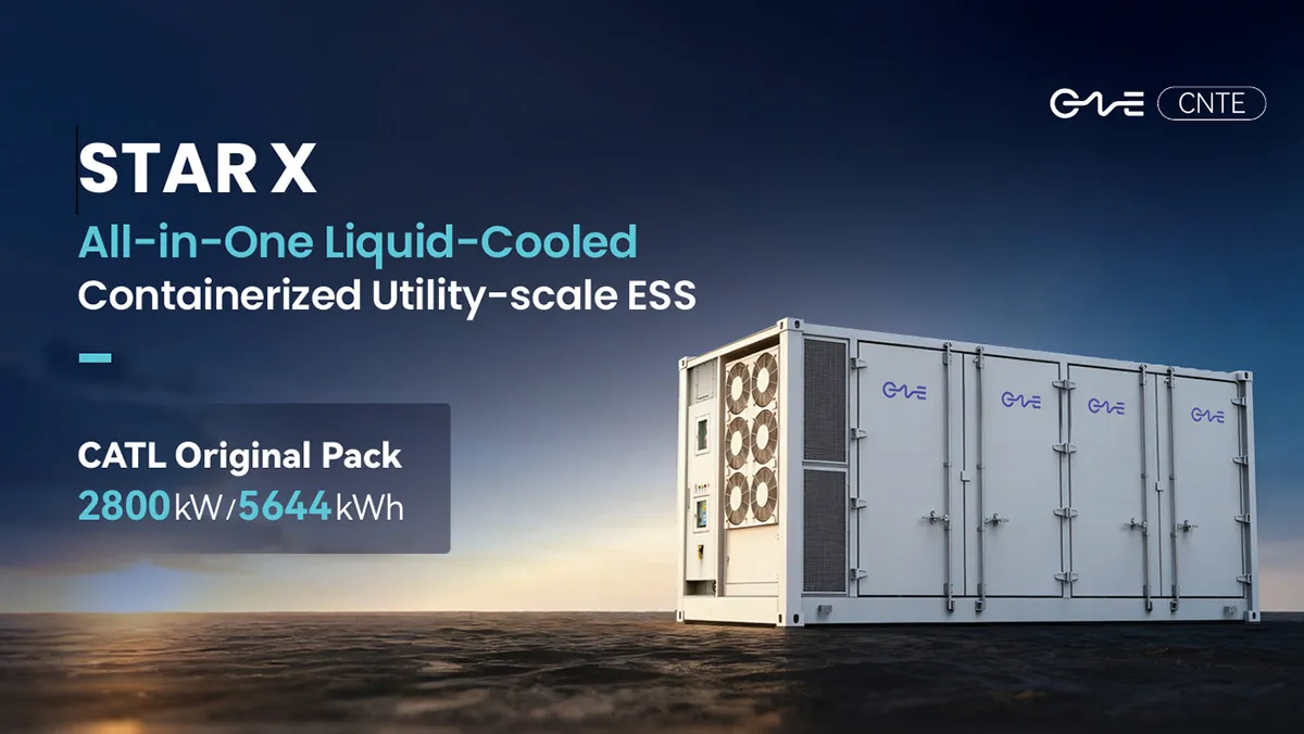
CNTE Launches STAR X Liquid-Cooled DC/AC Integrated Energy Storage System at Intersolar Europe 2026
Jul 06, 2026 -
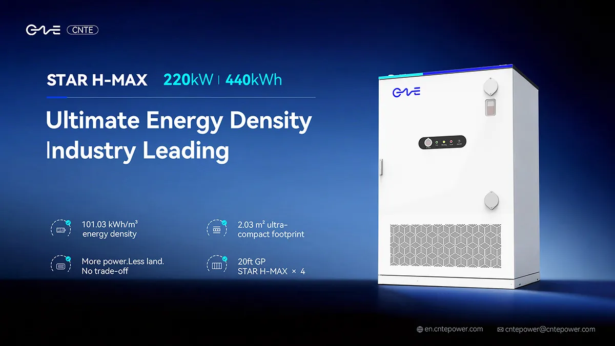
CNTE Unveils New STAR H-MAX Liquid-Cooled C&I ESS at Intersolar Europe 2026
Jun 23, 2026 -
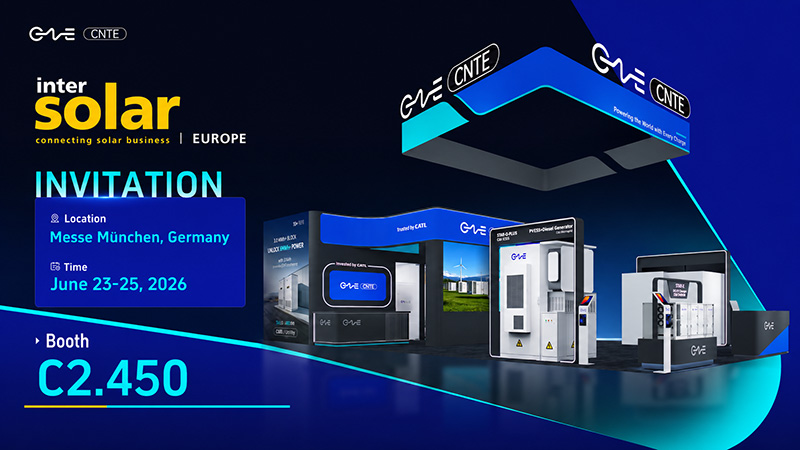
CNTE to Participate in Intersolar Europe 2026
May 20, 2026 -
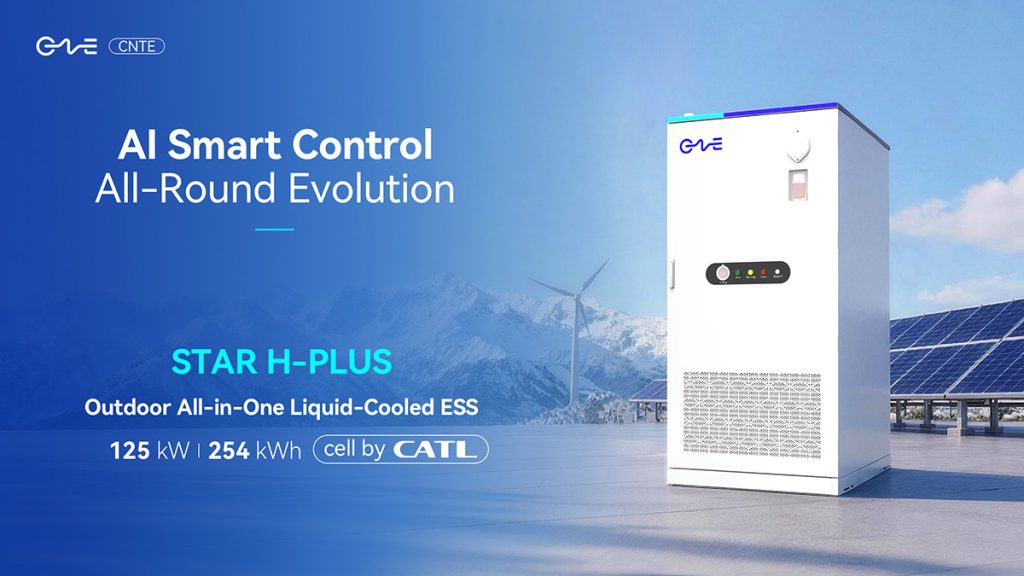
CNTE at KEY ENERGY 2026: Showcases STAR H-PLUS Outdoor Liquid-Cooled Energy Storage System
Mar 05, 2026 -

CNTE Honored as 2025 Forbes China Leading Global Brand
Jul 06, 2026 -
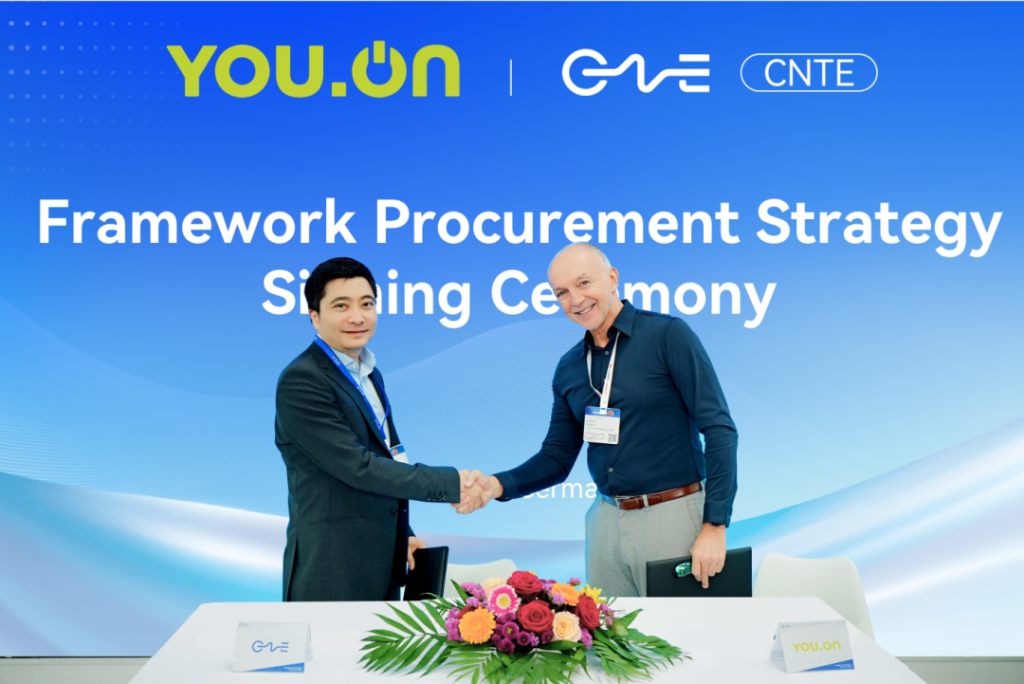
CNTE & YOU.ON Partner to Expand Storage Markets
May 19, 2025 -

CNTE Unveils Energy Storage Lineup at Solartech 2025
May 19, 2025 -
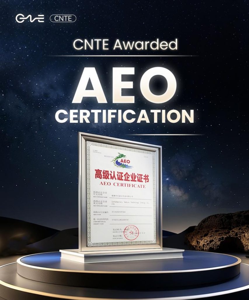
CNTE awarded AEO certification
Jul 06, 2026 -
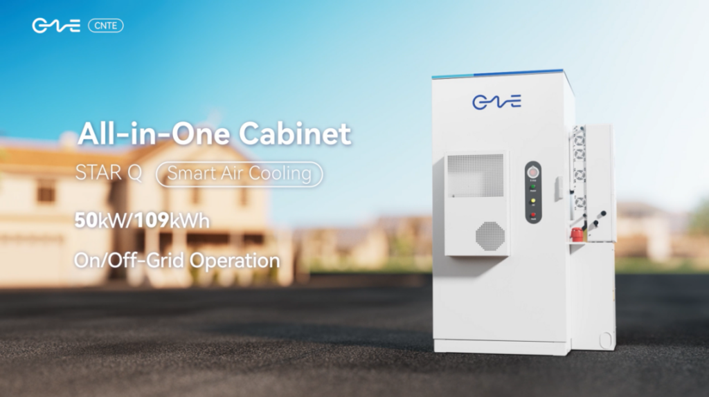
CNTE New Product Launch STAR Q
Jan 15, 2025 -

CNTE Named to Forbes China 2024 Top 30 Go-International Brands
Jul 06, 2026
