
Standalone BESS Architecture: Utility-Scale Engineering & Grid Economics
The global transition toward intermittent renewable energy sources has fundamentally altered transmission and distribution network dynamics. As synchronous thermal generation retires, electrical grids experience unprecedented volatility in system frequency, voltage stability, and line congestion. The deployment of a standalone bess has transitioned from a specialized grid trial to a foundational component of modern utility infrastructure, providing decoupleable flexibility directly at critical transmission nodes.
Unlike co-located storage tied to solar or wind generation assets, independent energy storage facilities operate without the physical constraints of on-site resource availability. They interface directly with the high-voltage transmission or medium-voltage distribution network, executing bilateral energy transfers driven purely by grid demand, capacity pricing signals, and ancillary services markets. Achieving institutional-grade bankability requires deep mastery over electrochemical characteristics, power conversion engineering, thermal dynamics, and sophisticated control topologies.
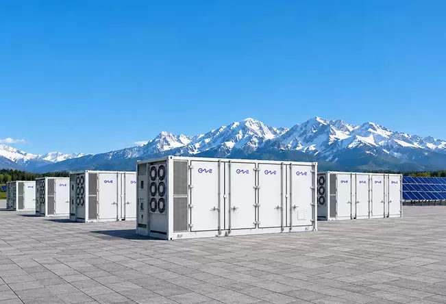
Electrochemical Core and Balance of Plant Architecture
At the center of utility-grade storage is the electrochemical cell. While alternative chemistries continue to emerge across laboratory environments, Lithium Iron Phosphate (LFP) remains the dominant technology for utility installations due to its exceptional thermal stability, structural integrity during cycling, and competitive levelized cost. The intrinsic olivine crystal structure of LFP offers robust chemical bonds, dramatically reducing oxygen release mechanisms under thermal stress compared to nickel-based formulations.
Moving from the cell level to practical containerized enclosures requires multiple tiers of isolation, structural stabilization, and monitoring. System integrators group individual prismatic cells into series-parallel modules, which are subsequently integrated into tall battery racks managed by a multi-tiered Battery Management System (BMS). The primary tier oversees cell-level voltage and temperature; the secondary tier monitors rack-level current, contactor states, and insulation resistance; the tertiary tier coordinates across multiple racks to communicate with the overall plant controller.
Thermal management dictates the longevity, throughput efficiency, and overall degradation trajectory of the asset. Modern design has moved decisively away from legacy forced-air cooling in favor of direct-to-cell liquid cooling systems. Liquid distribution plates provide uniform heat dissipation across every module, keeping cell-to-cell temperature variations within a strict ±2°C delta. Controlling this thermal delta eliminates uneven degradation rates across the pack, which would otherwise prematurely limit total usable capacity during high-C-rate operations.
Safety frameworks dictate structural layout and physical spacing. Tier-one engineering designs integrate comprehensive passive and active protections, adhering to UL 9540, UL 9540A, and NFPA 855 standards. These include:
- Multi-stage early off-gas detection utilizing specialized hydrogen and carbon monoxide sensors to detect cell failure prior to thermal excursions.
- Dedicated deflagration venting systems compliant with NFPA 68 to safely direct overpressure away from adjacent enclosures.
- Internal aerosol or clean-agent fire suppression paired with external dry-pipe water deluge connections for emergency response isolation.
- IP67-rated sealed enclosures designed to withstand environmental ingress, high humidity, and aggressive particulate exposure.
Power Conversion Topologies and Grid-Forming Inverters
The interface between the direct current (DC) battery blocks and the alternating current (AC) grid determines both round-trip efficiency (RTE) and electrical response times. The optimal topology for a utility-scale standalone bess involves a calculated choice between centralized inverter stations and distributed string power conversion systems (PCS).
Centralized architectures aggregate multi-megawatt DC blocks into large-scale skid-mounted inverters. This design offers lower upfront capital expenditure per megawatt and consolidates maintenance points into fewer physical enclosures. However, centralized systems expose the plant to higher mismatch losses when battery racks age unevenly, and a single inverter outage removes significant operational capacity from the market.
Distributed string architectures, conversely, integrate dedicated PCS units at the rack or small-cluster level. By executing Maximum Power Point Tracking (MPPT)-style state-of-charge equalization across isolated DC segments, string inverters maximize energy throughput and minimize systemic downtime. In string-based configurations, a single PCS failure leaves the remainder of the field entirely operational, preserving grid service contracts and cash flow predictability.
Simultaneously, the evolving electrical grid demands a paradigm shift in inverter controls: moving from grid-following (GFL) to grid-forming (GFM) architectures. Standard GFL inverters rely on Phase-Locked Loops (PLL) to track the voltage and frequency vectors of the host grid. In areas with low short-circuit ratios (SCR) and depleted synchronous inertia, GFL inverters face synchronization instability, sometimes exacerbating system oscillations.
Grid-forming inverters, operating via virtual synchronous machine (VSM) or droop-control algorithms, internally generate voltage source references. They exhibit instantaneous synthetic inertia, supply critical sub-transient fault currents, and can facilitate black start restoration for regional grids. Engineering partners such as CNTE (Contemporary Nebula Technology Energy Co., Ltd.) solve these interface dynamics through integrated power conversion and high-tier battery management layers designed to ensure continuous network stability under low-inertia grid conditions.
Monetization Pathways and Value Stacking Dynamics
The financial viability of non-co-located storage rests on diversified operational value stacking. Unlike systems constrained by co-located generation profiles, an unconstrained standalone bess optimizes its charging cycles according to complex merchant market algorithms, capacity auctions, and high-speed ancillary service opportunities.
Wholesale Arbitrage
Arbitrage requires buying wholesale electrical energy during pricing troughs and discharging during extreme peak pricing windows. Success depends not only on electricity market spreads, but on the precise calculation of marginal degradation costs per cycle. If the spread between charge and discharge does not exceed the Levelized Cost of Storage (LCOS) wear cost, cycling destroys asset value. Sophisticated Energy Management Systems (EMS) utilize predictive market models to balance wholesale dispatch against warranty degradation limits.
Frequency Containment and Regulation
Frequency regulation markets—such as Dynamic Containment, Enhanced Frequency Response (EFR), or RegD—demand rapid active power output in response to grid frequency excursions. Sub-second response times are standard. Standalone batteries excel in these markets because electrochemical reactions and power electronics adjust load states far faster than conventional mechanical thermal turbines, commanding premium capacity payments for continuous readiness.
Capacity Mechanisms and System Adequacy
Grid operators establish capacity markets to secure long-term system resource adequacy. Independent storage systems earn predictable, availability-based monthly revenue simply by holding contracted capacity reserves ready for dispatch during stressed system hours. Derating factors dictate the exact capacity accreditation an asset receives, which varies based on storage duration (e.g., 2-hour, 4-hour, or 8-hour configurations).
Plant-Level System Integration and Control Hierarchy
The overarching profitability and operational reliability of large storage plants hinge on digital architecture. A modern facility employs an integrated, multi-tier supervisory control infrastructure:
- Device Control (Level 0/1): Direct embedded firmware running within individual battery modules and PCS units, executing safety routines, gating sequences, and millisecond-level protections.
- Supervisory Control and Data Acquisition (SCADA) (Level 2): Station-level programmable logic controllers (PLCs) collecting telemetry, managing thermal systems, HVAC, site security, and medium-voltage switchgear.
- Energy Management System (EMS) (Level 3): Advanced algorithmic control running localized optimization routines, managing state-of-charge (SoC) balance, processing real-time utility dispatch orders, and adjusting real and reactive power targets.
- Cloud-Based Fleet Optimization (Level 4): Machine-learning analytics monitoring degradation rates across parallel assets, predicting component wear, calculating battery state-of-health (SoH), and interfacing with commercial bidding platforms.
Substation integration introduces another critical engineering dimension. Stepping medium voltage (typically 33kV or 34.5kV) up to transmission levels (110kV, 220kV, 400kV) requires specialized pad-mounted step-up transformers, gas-insulated switchgear (GIS), grounding transformers, and reactive power compensation equipment. Managing harmonics, harmonic distortion limits (IEEE 519), and reactive power capability curves at the point of common coupling (PCC) requires rigorous electrical transient analyzer program (ETAP) modeling during the front-end engineering design (FEED) phase.
Lifecycle Degradation Modeling and Capacity Augmentation
Battery capacity degrades inevitably over time through two primary mechanisms: calendar aging and cycling aging. Calendar degradation occurs independent of throughput, driven primarily by ambient temperature, elevated states of charge, and internal electrolyte decomposition. Cycling degradation stems from mechanical stresses induced by lithium-ion intercalation and de-intercalation, forming solid electrolyte interphase (SEI) layer growth, lithium plating, and impedance increases.
When modeling asset life across a typical 15- to 20-year project horizon, asset managers evaluating standalone bess projects must model cell degradation alongside targeted capital expenditure programs. Two primary strategies exist for managing lifecycle capacity decline:
Overbuild Strategy: The developer installs substantial excess capacity on Day 1 to ensure the plant meets its rated interconnect capacity at Year 10 without hardware additions. While this simplifies civil works, it incurs high initial CAPEX and accelerates calendar aging on cells that are underutilized during the project's early operating years.
Planned Augmentation Strategy: The developer sizes the plant precisely for initial contractual requirements, leaving physical footprints, balance-of-plant interfaces, and inverter capacity available for sequential additions at Year 5, 10, or 15. Equipment manufacturers like CNTE (Contemporary Nebula Technology Energy Co., Ltd.) structure modular cabinet designs to streamline this multi-stage capital expenditure, allowing asset owners to capture future price decreases in battery manufacturing while matching degradation curves accurately to commercial obligations.
Frequently Asked Questions (FAQ)
How does a standalone bess differ economically from co-located solar-plus-storage?
A co-located system shares land, interconnection hardware, and permitting expenses with a generation source, often capitalizing on shared tax frameworks or lowering balance-of-plant costs. However, its charging cycles are heavily dictated by the co-located asset's generation profile, and it often faces location constraints dictated by solar irradiance or wind availability. A standalone facility can be sited strategically at high-congestion grid nodes, electrical substations, or industrial load centers. This enables complete freedom to charge from the grid at optimal pricing points and sell into high-value ancillary services markets without restriction.
What are the primary factors affecting Round-Trip Efficiency (RTE)?
System-level AC-to-AC round-trip efficiency typically ranges between 84% and 88%, which is notably lower than raw cell-level DC-to-DC efficiency (often exceeding 95%). The disparity arises from cumulative auxiliary loads and electrical conversion stages: auxiliary power consumption for liquid chillers and thermal systems, internal module resistance, PCS switching and conduction losses, and step-up transformer magnetic core and copper losses. Optimizing RTE requires low-parasitic liquid cooling systems, advanced silicon carbide (SiC) power semiconductors, and optimized transformer loading schedules.
What grid connection criteria must be met for multi-megawatt standalone assets?
Developers must satisfy rigorous regional grid interconnection codes before achieving commercial operation status. Key parameters include fault-ride-through (FRT) capabilities—enabling the system to stay online during severe voltage dips—active power ramp rate controls, dynamic reactive power support (VAR support), power factor regulation at the Point of Interconnection (POI), and total harmonic distortion (THD) limitations. Interconnection studies assess Short Circuit Ratios (SCR) to ensure that the converter controls do not trigger localized sub-synchronous resonance.
How is system degradation managed over a 15- to 20-year project horizon?
Managing degradation combines optimized operational controls and physical plant expansion. Operational control relies on dynamic EMS algorithms that prevent high average states of charge, moderate cell temperatures via predictive cooling, and adjust C-rates based on market pricing vs. cell wear cost. Physically, degradation is counteracted by planned capacity augmentation cycles, where new modular battery strings are integrated into reserved bays to restore lost MWh capacity without replacing the core balance-of-plant infrastructure.
Which cooling architecture delivers superior performance in high-C-rate operations?
Direct-to-pack liquid cooling significantly outperforms forced-air cooling in high-power applications (1C and higher). Water-glycol fluid loops possess a volumetric heat capacity several thousand times greater than air, allowing them to absorb rapid thermal spikes without large temperature gradients. Liquid cooling holds every cell within tight operational tolerances, suppresses localized hotspot formation, decreases auxiliary power consumption under extreme ambient temperatures, and directly prolongs usable calendar life.
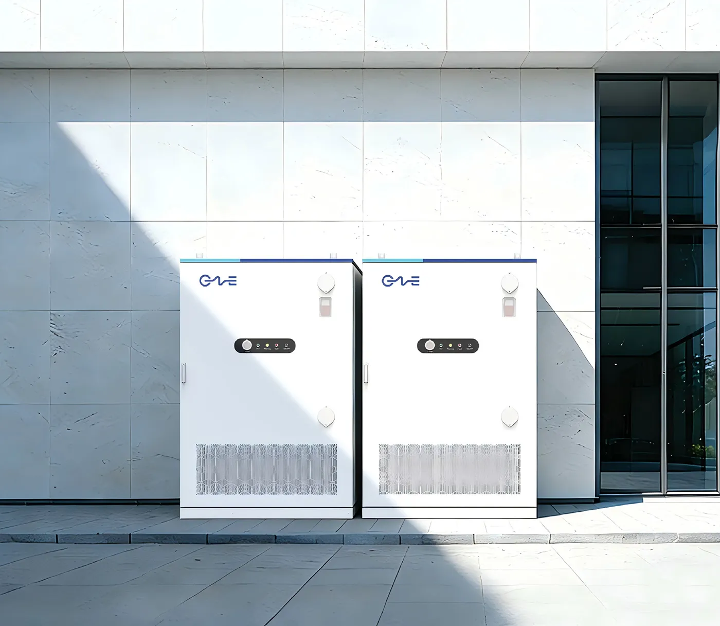
Securing Infrastructure-Grade Energy Storage Assets
Deploying an institutional-grade standalone bess requires deep domain expertise spanning power electronics, electrochemical longevity, localized grid interconnection procedures, and multi-market optimization software. Balancing the complex relationship between capital expenditure, auxiliary parasitic loads, system availability, and augmentation schedules dictates whether an operational asset achieves its financial metrics over decades of operation.
Organizations seeking to evaluate plant design, utility interconnect compliance, and optimized hardware configurations can collaborate with CNTE (Contemporary Nebula Technology Energy Co., Ltd.) to transition projects from feasibility analysis to commercial operation. Submit a project specification sheet or direct inquiry to initiate a comprehensive technical review of your planned utility-scale or industrial storage deployment.
Get in Touch
Recent Posts
-
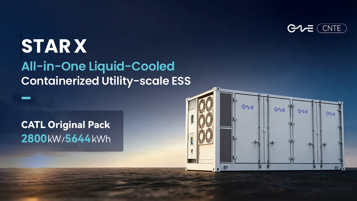
CNTE Launches STAR X Liquid-Cooled DC/AC Integrated Energy Storage System at Intersolar Europe 2026
Jul 06, 2026 -
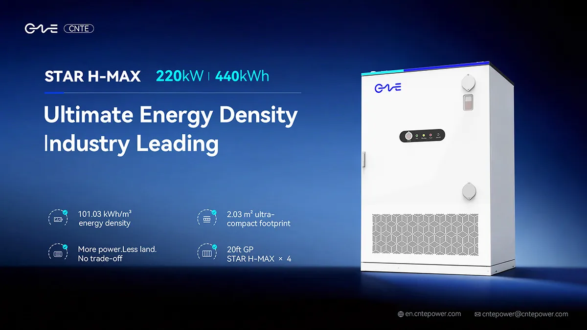
CNTE Unveils New STAR H-MAX Liquid-Cooled C&I ESS at Intersolar Europe 2026
Jun 23, 2026 -
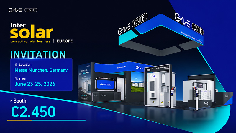
CNTE to Participate in Intersolar Europe 2026
May 20, 2026 -
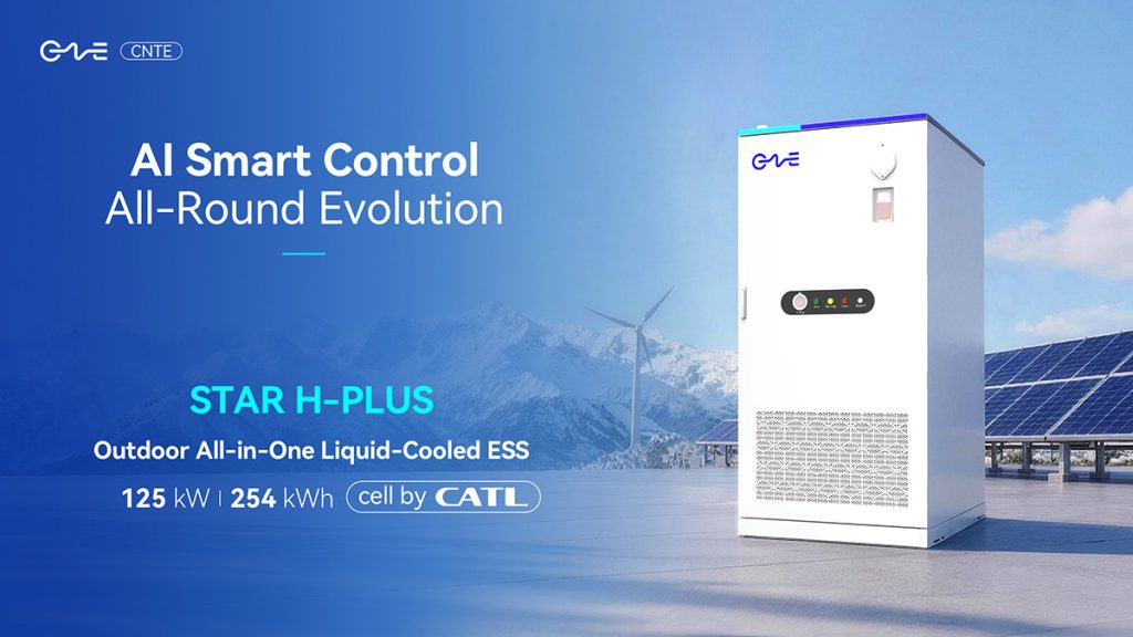
CNTE at KEY ENERGY 2026: Showcases STAR H-PLUS Outdoor Liquid-Cooled Energy Storage System
Mar 05, 2026 -

CNTE Honored as 2025 Forbes China Leading Global Brand
Jul 06, 2026 -

CNTE & YOU.ON Partner to Expand Storage Markets
May 19, 2025 -

CNTE Unveils Energy Storage Lineup at Solartech 2025
May 19, 2025 -

CNTE awarded AEO certification
Jul 06, 2026 -
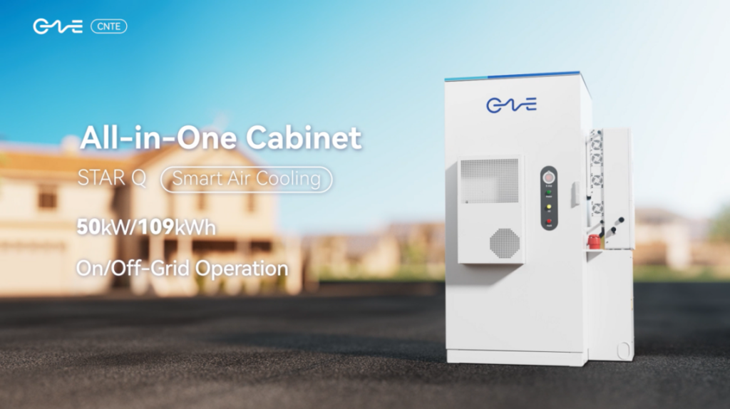
CNTE New Product Launch STAR Q
Jan 15, 2025 -

CNTE Named to Forbes China 2024 Top 30 Go-International Brands
Jul 06, 2026
