
BESS Application Guide: Engineering Utility & Industrial Storage Systems
The global transition toward non-synchronous renewable power generation has structurally transformed the operational requirements of transmission networks and industrial power systems. Intermittent solar photovoltaic and wind resources introduce severe frequency instability, reactive power imbalances, and steep ramping gradients into legacy electrical grids. Resolving these operational challenges necessitates fast-acting, high-energy-density storage infrastructure capable of millisecond-level dynamic response. Evaluating any utility or commercial bess application requires an in-depth understanding of electrochemical storage systems, conversion topologies, multi-tiered protection mechanisms, and intelligent dispatch layers.
Contemporary stationary storage relies primarily on Lithium Iron Phosphate (LiFePO4 or LFP) battery cell chemistry due to its superior structural stability, low degradation under intensive thermal cyclic stress, and prolonged operating lifetimes. Maximizing the economic lifecycle of electrochemical assets requires modern balance-of-plant engineering to optimize the entire electrical train. This encompasses everything from cell-to-pack integration and high-voltage rack architecture to bidirectional power conversion systems (PCS), microgrid controllers, and comprehensive energy management systems (EMS).
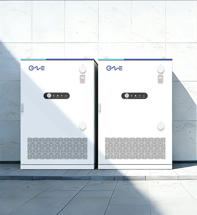
Electrochemical and Electrical Topologies of Stationary Storage
At the foundation of any large-scale energy storage deployment lies the cell-to-grid electrical architecture. Battery cells are systematically grouped into series strings to achieve target DC bus voltages—typically ranging between 1000V DC and 1500V DC in modern utility platforms—and arranged in parallel to scale current and energy capacity. High DC voltages decrease transmission losses through busbars and power cables, allowing for reduced copper volume and optimized thermal dissipation across high-capacity enclosures.
The interface between the electrochemical battery racks and the alternating current (AC) grid depends on central or distributed bidirectional Power Conversion Systems. Centralized configurations consolidate multiple DC battery strings into a single large-capacity inverter block, reducing initial capital expenditures on balance-of-plant equipment. In contrast, distributed or string-inverter architectures dedicate isolated maximum power tracking and converter channels to individual battery racks or containers. This distributed layout limits circulating currents between strings of varying internal impedance, minimizes capacity mismatch losses over years of cycling, and substantially enhances asset availability during scheduled maintenance routines.
System coordination is governed by a three-tiered digital infrastructure:
- Battery Management System (BMS): Operates at the cell, module, and rack level to monitor voltage, temperature, and current in real time, calculating dynamic State of Charge (SoC) and State of Health (SoH) metrics while managing passive or active cell balancing.
- Power Conversion System (PCS) Controller: Executes rapid digital signal processing commands to adjust four-quadrant active (P) and reactive (Q) power injection within milliseconds, operating in either grid-following or grid-forming mode.
- Energy Management System (EMS): Orchestrates macro-level system dispatch, parsing market pricing signals, weather forecasts, site telemetry, and operational constraints to optimize revenue generation and asset preservation.
Utility-Scale BESS Application: Grid Stability, Ancillary Services, and Wholesale Arbitrage
The deployment of energy storage assets directly onto high-voltage transmission and sub-transmission networks provides regional grid operators with essential operational flexibility. As thermal power plants retire, the loss of physical rotational inertia diminishes the ability of the power system to arrest rapid frequency shifts during unexpected generator trips or line failures. In this operating environment, the utility-scale bess application functions as a synthetic inertia source and high-speed ancillary service asset.
Frequency containment reserves (FCR) and automatic frequency restoration reserves (aFRR) demand sub-second ramp rates that thermal turbines cannot match. Grid-scale batteries operating with droop curves continuously monitor local AC frequency via phase-locked loops (PLL) or direct voltage synthesis. When system frequency deviates from nominal setpoints (50 Hz or 60 Hz), the storage system injects or absorbs real power within 100 to 200 milliseconds, arresting the rate of change of frequency (RoCoF) and stabilizing the broader transmission area.
Energy arbitrage models capitalize on price differentials across wholesale day-ahead and real-time spot electricity markets. By charging during periods of negative or suppressed pricing driven by high solar irradiance or strong nighttime wind output, the system discharges during peak load windows when locational marginal prices (LMP) escalate. Transmission and distribution deferral provides an additional utility value stream: by injecting power directly at overloaded distribution substations during peak demand intervals, network utilities can defer or bypass costly transformer replacements and circuit reconductoring projects.
Behind-the-Meter BESS Application: Tariff Optimization, Fleet Charging, and Microgrids
Commercial, industrial, and institutional facilities face high utility expenditures driven by demand charges—tariff structures that penalize sites based on their single highest power draw recorded within fifteen- or thirty-minute intervals over a billing cycle. Implementing a behind-the-meter bess application serves as an effective technical mechanism to control these operating expenses through algorithmic peak shaving.
Peak shaving requires low-latency telemetry at the main facility switchgear. When industrial inductive loads—such as large compressors, arc furnaces, or centralized HVAC chillers—threaten to breach a preset power threshold, the local controller commands the battery to discharge instantaneously. This localized power injection offsets grid import, leveling the facility load profile and mitigating peak demand tariffs without interrupting plant operations.
The rapid electrification of commercial commercial vehicle fleets introduces severe localized load constraints onto standard utility interconnects. Depots deploying multi-megawatt DC fast-charging plazas often face grid connection queues spanning several years. Integrating on-site energy storage decouples the grid connection from transient vehicle charging spikes:
- The battery trickle-charges from the utility grid or local rooftop solar arrays during prolonged dwell periods.
- During simultaneous, high-power DC fast-charging sessions, the battery system buffers the peak, delivering high-current discharge to vehicles without exceeding utility capacity limits.
- Integrated microgrid architectures switch smoothly to islanded operation during utility outages, using grid-forming inverters to provide uninterrupted black-start and backup power to high-priority industrial assembly lines.
Technical System Design Parameters and Performance Metrics
Designing a reliable energy storage installation requires balancing key electromechanical parameters against operational use cases. Matching battery pack sizing with the target bess application demands rigorous analysis of C-rate dynamics, round-trip efficiency (RTE), and capacity fade trajectories over operational lifecycles.
The C-rate defines the ratio of charge or discharge current relative to total nominal capacity. Short-duration power-oriented assets (such as primary frequency response units) utilize high C-rates (1C to 4C), delivering full capacity within fifteen to sixty minutes. Conversely, wholesale arbitrage, energy shifting, and multi-hour microgrid resiliency favor duration over raw power, employing lower C-rates (0.25C to 0.5C) spanning continuous four- to eight-hour discharge profiles. Higher C-rates generate elevated internal Joule heating ($I^2R$ losses) across internal cell terminals, accelerating electrochemical degradation if thermal management systems are improperly sized.
Round-trip efficiency represents the net energy retrievable from the storage system relative to the gross energy supplied during charging. System-level RTE accounts for several cumulative parasitic and thermodynamic losses:
- Electrochemical overpotential and internal cell impedance during charge-discharge cycling.
- Semiconductor conduction and switching losses within bidirectional inverter IGBT or SiC modules.
- Medium-voltage step-up transformer core and copper losses.
- Continuous auxiliary power consumption drawn by liquid cooling chillers, ventilation fans, BMS boards, and supervisory industrial control panels.
Engineering tier-one installations requires precise degradation modeling. Battery degradation occurs through two concurrent mechanisms: calendar aging (driven by resting cell temperature and baseline state-of-charge over time) and cyclic aging (dictated by cumulative throughput, depth of discharge, and operational thermal fluctuations). Advanced system designs, such as those engineered by CNTE (Contemporary Nebula Technology Energy Co., Ltd.), leverage intelligent thermal distribution to keep core cell temperature variances within strict margins of 2 to 3 degrees Celsius across the entire pack, mitigating localized accelerated aging and string imbalance.
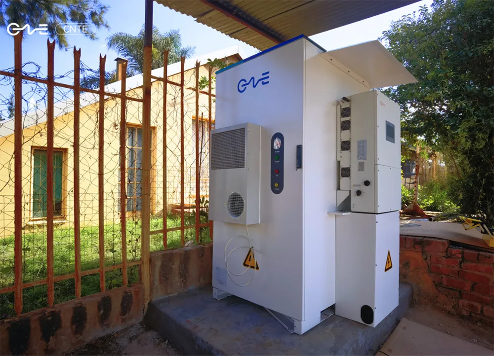
Advanced Thermal Management and Safety Engineering Architecture
Large-scale energy density demands robust thermal and structural engineering to prevent localized thermal runaway events. Liquid cooling architectures have displaced legacy forced-air cooling in high-utilization utility and commercial enclosures due to the superior specific heat capacity of water-glycol mixtures compared to air.
Liquid cooling plates positioned directly adjacent to cell bodies maintain uniform thermal profiles across varying ambient environmental conditions, spanning -30 degrees Celsius to +55 degrees Celsius. Eliminating internal hotspot generation extends aggregate cycle longevity, preserves high system-level round-trip efficiency, and minimizes internal parasitic cooling loads during high-ambient operation.
Comprehensive fire protection and life-safety engineering adhere to strict international frameworks, including NFPA 855, UL 9540, and UL 9540A unit-level fire propagation test standards. Multi-stage structural containment integrates the following layers:
- Early Stage Detection: Multi-gas aspiration sensors identify trace off-gassing components—including carbon monoxide (CO), hydrogen ($H_2$), and volatile organic compounds (VOCs)—long before temperature spikes or smoke generation manifest.
- Active Fire Suppression: Clean agent gaseous systems (such as Novec 1230) knock down localized module electrical fires, paired with integrated dry-pipe or direct-to-rack water deluge infrastructure designed to absorb heat and prevent propagation across adjacent racks.
- Passive Deflagration Venting: Top-mounted or side-mounted pressure relief explosion panels vent sudden internal pressure surges outward away from maintenance corridors, maintaining structural integrity of the main enclosure.
CNTE integrates multi-tiered sensor suites with edge-computing platforms that evaluate cell impedance anomalies in real time. Isolating electrical faults at the sub-rack level prevents system shutdowns and minimizes unrecoverable degradation across mission-critical utility installations.
Frequently Asked Questions
What criteria determine the choice between AC-coupled and DC-coupled systems in solar-plus-storage projects?
The decision hinges on project topology, retrofit status, and operational objectives. AC-coupled architectures place the storage system and solar PV on separate inverters, connecting them at the AC bus. This provides complete operational independence, simplifies brownfield retrofits to existing solar fields, and enables independent maintenance. DC-coupled systems integrate PV strings and battery modules onto a shared DC bus feeding a unified central inverter via DC-DC buck-boost converters. DC coupling achieves higher overall solar charging round-trip efficiency by bypassing double DC-AC-DC conversions and captures clipped peak solar generation that would otherwise exceed AC inverter limits.
How does Depth of Discharge (DoD) directly impact the operational lifecycle of an LFP battery system?
Depth of Discharge refers to the percentage of total capacity withdrawn during a discharge cycle. Operating constantly at 100% DoD accelerates chemical degradation of cathode-anode structural interfaces and thickens the Solid Electrolyte Interphase (SEI) layer due to volumetric expansion and contraction. Restricting continuous cycling to an 80% or 90% operational DoD dynamic envelope can increase available cycle life from approximately 5,000–6,000 cycles to over 8,000–10,000 cycles, lowering the Levelized Cost of Storage (LCOS) over a 15- to 20-year project lifespan.
What is the difference between grid-following and grid-forming inverter modes?
Grid-following inverters require an existing, stable voltage and frequency reference supplied by traditional rotating generators to maintain synchronization. They track the grid phase angle via Phase-Locked Loops (PLL) and inject synchronized current. Grid-forming inverters act as true independent AC voltage sources. Utilizing internal virtual synchronous machine (VSM) algorithms, they establish voltage and frequency setpoints autonomously, inject synthetic inertia instantaneously during grid disruptions, and provide essential black-start capability to re-energize collapsed grid sections without external assistance.
How are parasitic auxiliary power losses factored into long-term system economics?
Auxiliary power consumption accounts for the steady electrical loads drawn by HVAC and liquid chillers, internal ventilation fans, electronic sensor networks, BMS controllers, illumination, and communication gateways. In high-ambient environments with legacy cooling, auxiliary power can consume 3% to 8% of daily system throughput. Factoring these continuous internal loads into financial modeling is necessary to calculate real-world project revenue, net energy throughput, and operational expenditure budgets across project lifetimes.
Which primary performance indicators define battery degradation during technical due diligence?
Technical due diligence focuses primarily on Capacity Retention (the remaining usable amphour or kilowatt-hour storage capacity relative to baseline nameplate specifications) and Internal Resistance / Equivalent Series Resistance (ESR). Rising ESR causes accelerated thermal generation during operation, increases round-trip efficiency losses, and creates higher voltage drop under peak load. Additional tracked indicators include coulombic efficiency, capacity fade curves plotted against cumulative megawatt-hour throughput, and the variance in individual cell balancing voltages across modules.
Engineering Optimization and Project Development
Deploying resilient, high-yield battery energy storage assets demands deep technical expertise spanning electrochemistry, high-voltage power engineering, grid interconnect standards, and advanced digital optimization. Selecting optimal components and designing robust balance-of-plant systems protects capital investments against premature degradation and changing market structures. Formulating a bankable bess application demands precision engineering, lifecycle analysis, and equipment built to rigorous global manufacturing certifications.
CNTE provides complete, technologically sophisticated energy storage platforms for commercial, industrial, and utility-scale projects worldwide. To discuss custom technical specifications, request detailed system integration drawings, or initiate an engineering consultation for your upcoming project, submit your technical parameters and procurement inquiry to our utility engineering team.
Get in Touch
Recent Posts
-
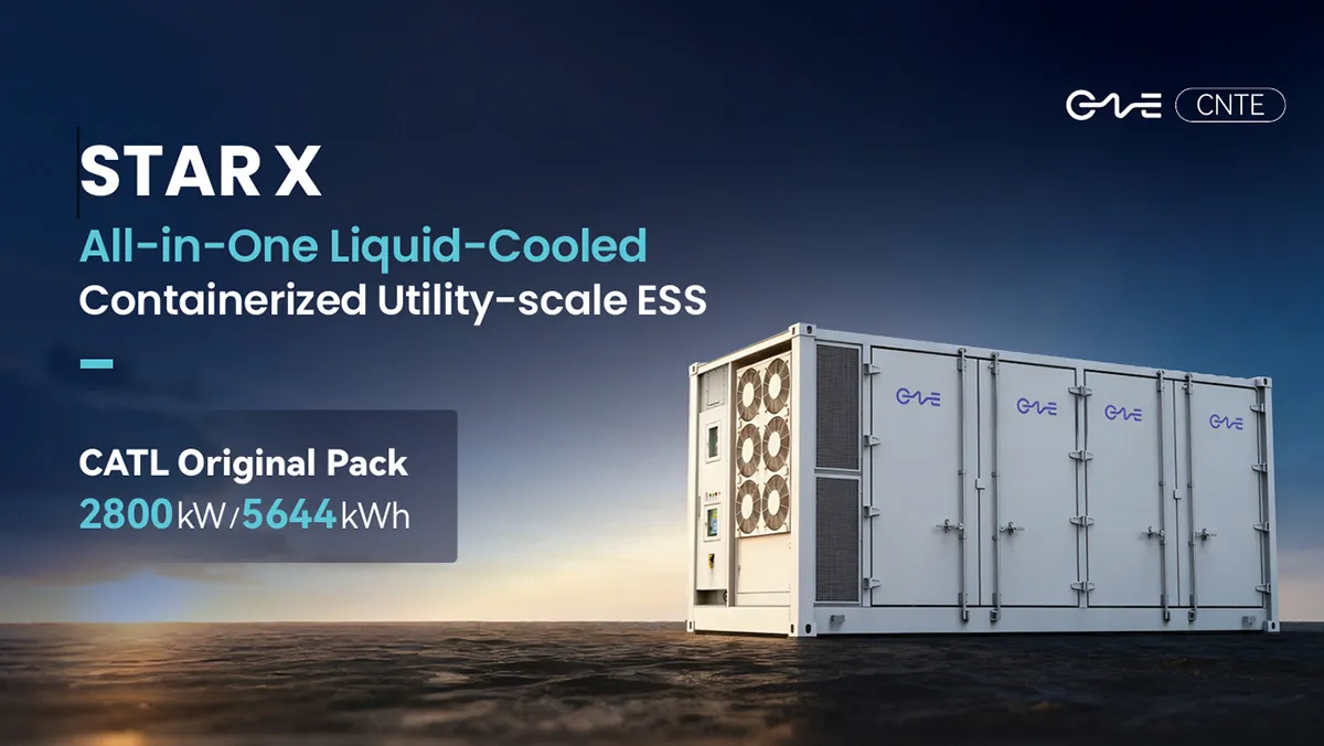
CNTE Launches STAR X Liquid-Cooled DC/AC Integrated Energy Storage System at Intersolar Europe 2026
Jul 06, 2026 -
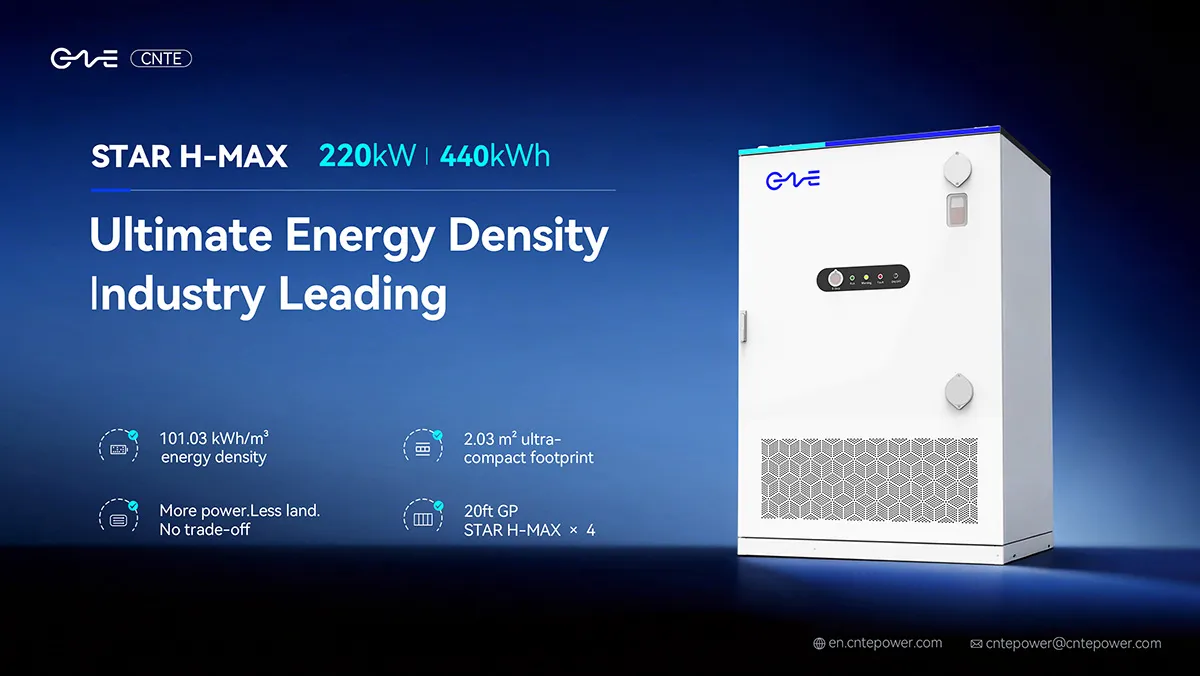
CNTE Unveils New STAR H-MAX Liquid-Cooled C&I ESS at Intersolar Europe 2026
Jun 23, 2026 -
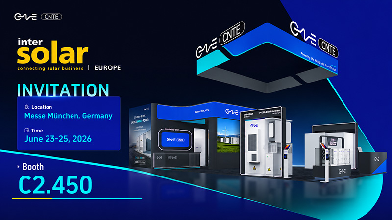
CNTE to Participate in Intersolar Europe 2026
May 20, 2026 -
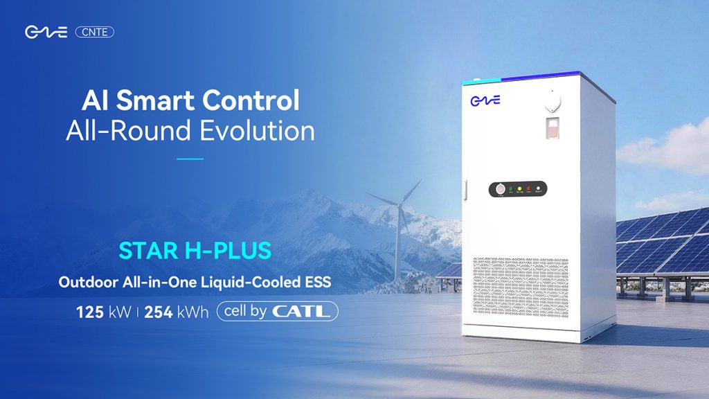
CNTE at KEY ENERGY 2026: Showcases STAR H-PLUS Outdoor Liquid-Cooled Energy Storage System
Mar 05, 2026 -

CNTE Honored as 2025 Forbes China Leading Global Brand
Jul 06, 2026 -

CNTE & YOU.ON Partner to Expand Storage Markets
May 19, 2025 -

CNTE Unveils Energy Storage Lineup at Solartech 2025
May 19, 2025 -
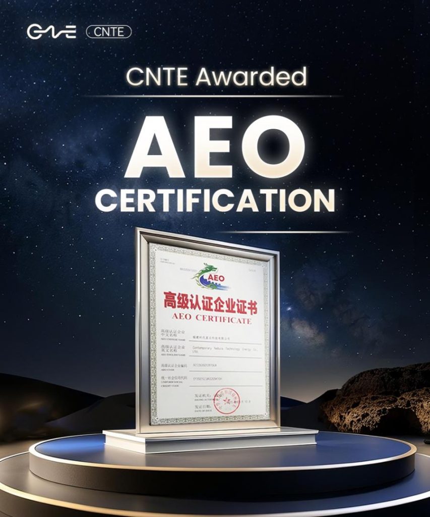
CNTE awarded AEO certification
Jul 06, 2026 -
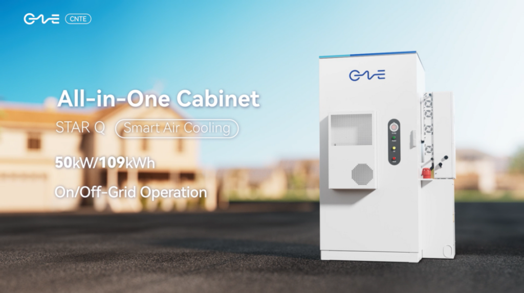
CNTE New Product Launch STAR Q
Jan 15, 2025 -

CNTE Named to Forbes China 2024 Top 30 Go-International Brands
Jul 06, 2026
