
Large Scale Batteries for Utility and Industrial Storage: Technical Analysis
The transition toward high-penetration renewable generation has transformed power system stability from a mechanical certainty into an active software and electrochemical control challenge. Where thermal generation historically supplied natural rotational inertia through synchronous machinery, modern transmission networks increasingly demand synthetic dynamics. Electrochemical energy storage systems deliver this capability. At the core of this transition are large scale batteries, serving as multi-functional grid assets capable of millisecond-level frequency containment, transmission congestion relief, and structural capacity firming across distributed and centralized networks.
Deploying these systems at megawatt and gigawatt scales requires deep technical integration spanning cell-level electrochemistry, thermodynamic controls, power conversion systems, and asset optimization software. System designers, utility operators, and industrial microgrid planners must navigate strict operational boundaries to balance asset life, round-trip efficiency, and system reliability.
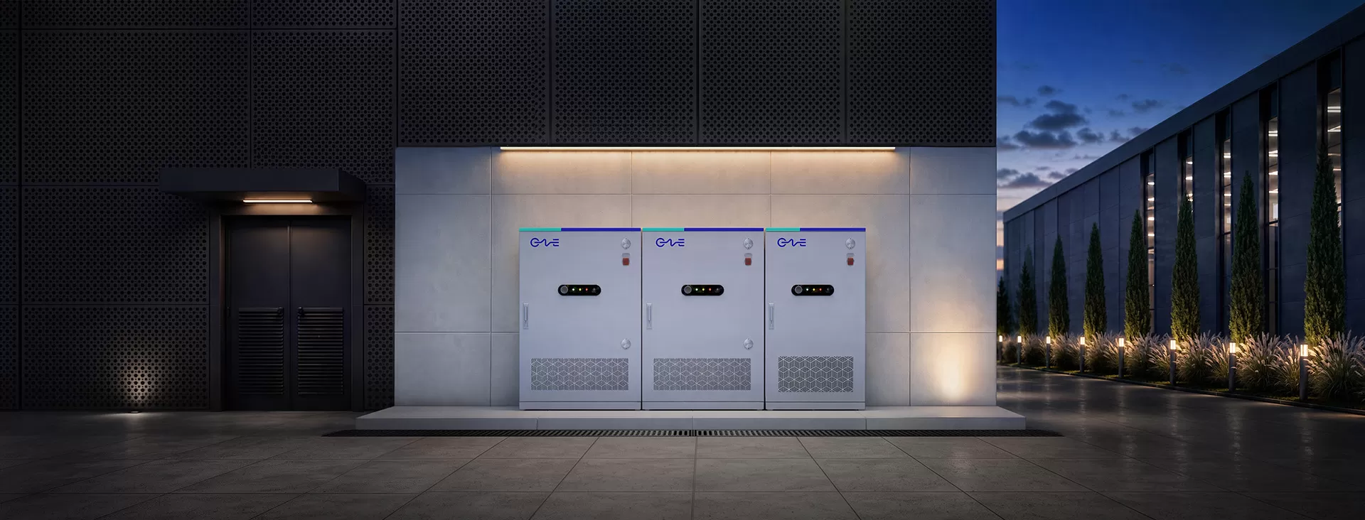
Electrochemical Paradigms and Degradation Kinetics
Cell selection dictates the boundary conditions of any energy storage facility. Lithium iron phosphate (LFP) has emerged as the prevailing standard across utility-scale and stationary industrial applications, supplanting nickel-manganese-cobalt (NMC) chemistries due to intrinsic crystal stability and lifecycle economics.
The olivine structure of LFP features robust P-O covalent bonds within the cathode, which significantly limits oxygen liberation under elevated temperatures. From an operational perspective, this structural integrity suppresses thermal runaway propagation, streamlining structural engineering and containment clearances. Beyond foundational safety metrics, the mechanical stress profile during lithiation and delithiation cycles shows marginal volume change compared to layered oxide chemistries, translating directly to extended cycle longevity exceeding 6,000 to 10,000 equivalent full cycles under controlled operating conditions.
Capacity loss is fundamentally driven by two interrelated phenomena: calendar degradation and cycling degradation. Calendar aging is primarily governed by the formation and continuous growth of the Solid Electrolyte Interphase (SEI) layer on the graphitic anode, a process accelerated by sustained elevated temperatures and high resting states of charge (SoC). Cycling degradation introduces mechanical fatigue, manifesting as active material particle micro-cracking and loss of lithium inventory (LLI). Mitigating these microstructural stresses requires precise operational controls through advanced Battery Management Systems (BMS), which regulate operational dynamic C-rates and maintain the battery within an optimal electrochemical window.
Thermal Management Architectures: Liquid vs. Air Phase Systems
Thermal stability across densely packed enclosures determines the degradation uniformity of large scale batteries. Temperature variances greater than 2 to 3 degrees Celsius between adjacent cells in a series string yield diverging internal impedance, uneven current distribution, and premature string-level capacity divergence.
Traditional forced-air cooling systems, while mechanically straightforward, struggle under high-rate discharge profiles and high-density footprints. Air maintains a low specific heat capacity and poor thermal conductivity, generating significant temperature gradients across large battery racks. Consequently, the utility sector has decisively pivoted toward closed-loop liquid cooling systems. Contemporary designs route chilled liquid plates directly beneath or between individual cells, ensuring consistent conductive heat extraction.
- Heat Dissipation Uniformity: Direct conductive contact minimizes core-to-surface delta T, preventing localized hotspots that accelerate active material decay.
- Auxiliary Power Consumption: Liquid systems exhibit lower parasitic loads under high ambient temperatures by using targeted volumetric heat capacity, optimizing overall system Round-Trip Efficiency (RTE).
- Volumetric Energy Density: Eliminating expansive airflow channels allows for tighter rack integration, elevating energy density per square meter to accommodate land-constrained substations.
- Environmental Isolation: Sealed liquid enclosures prevent external particulate, chemical, and moisture ingress, maintaining an internal environment that complies with rigorous ingress protection specifications.
Leading system integrators such as CNTE (Contemporary Nebula Technology Energy Co., Ltd.) leverage advanced liquid cooling circuits engineered to harmonize thermal fields across extensive storage footprints, securing stable operational profiles across diverse environmental baselines.
Power Conversion Systems and Grid-Forming Control Paradigms
The interface between DC battery arrays and the medium-voltage AC grid relies on the Power Conversion System (PCS). Modern installations are defined by two dominant inverter configurations: centralized architectures and distributed string architectures.
Centralized architectures aggregate multiple DC strings to a single, high-capacity inverter skid (typically 1.5 MW to 4 MW). While offering lower initial capital cost per megawatt and consolidated operations maintenance interfaces, centralized configurations can experience mismatch losses when battery racks age unevenly, pulling overall string performance down to the weakest rack's capacity. Distributed string architectures attach independent, smaller PCS units directly to individual battery racks or smaller clusters. This decoupling provides maximum Power Point Tracking (MPPT)-like flexibility, allows hot-swappable modular maintenance, and eliminates cross-string circulation currents.
Beyond hardware topology, the control software within the PCS determines its value to the transmission system:
- Grid-Following (GFL) Controls: Inverter phase-locked loops (PLL) synchronize to a pre-existing AC voltage waveform provided by external synchronous generators. If the grid suffers severe line faults or sudden trips, GFL inverters can struggle to remain synchronized during low-short-circuit-ratio (SCR) events.
- Grid-Forming (GFM) Controls: The inverter operates as an independent voltage source, setting its own voltage amplitude and internal frequency vector. Using virtual synchronous machine (VSM) algorithms, GFM systems respond to instantaneous frequency deviations by injecting synthetic inertia into the transmission network without requiring a reference signal.
- Black Start Capability: Grid-forming systems can energize dead busbars, supply the magnetization current for local transformers, and coordinate downstream generation pick-up following regional system collapses.
System Architectures: Battery Management and System Protection Topologies
Deploying storage infrastructure requires a multi-layered telemetry and protection stack capable of isolating electrical faults in microseconds. The control framework is traditionally segmented into a three-tier hierarchy: the cell-level BMS (Slave/Module Unit), the rack-level BMS (Master/Pack Unit), and the system-level BMS (Array/System Controller).
The primary layer executes continuous cell-level voltage and temperature tracking, paired with passive or active cell balancing circuits. The secondary layer manages string-level DC contactors, insulation monitoring, and cumulative State of Charge (SoC) and State of Health (SoH) algorithmic calculation. The tertiary layer aggregates these rack states, interfacing directly with the plant-level Energy Management System (EMS) via industrial fieldbus protocols such as Modbus TCP/IP, IEC 61850, or DNP3.
Electrical safety mechanisms operate across several domains:
- Short-Circuit Protection: High-speed semiconductor fuses paired with motorized DC breakers designed to interrupt DC fault currents with significant inductive energy without sustained arcing.
- Insulation Monitoring Devices (IMDs): Continuous measurement of leakage currents between floating DC rails and the earth ground, flagging early dielectric breakdown in cable jackets or cooling interfaces.
- Deflagration and Gas Detection: Advanced off-gas monitoring systems detecting early trace emissions of hydrogen, carbon monoxide, and volatile organic compounds (VOCs) prior to thermal escalation, automatically triggering ventilation routines and localized fire mitigation protocols.
Through robust multi-tier system designs, providers such as CNTE deliver high-voltage DC protection systems that comply with stringent global safety and performance benchmarks, including UL 9540, UL 9540A, and IEC 62933.
Grid-Scale and Industrial Application Profiles
The commercial deployment of large scale batteries is anchored by their operational versatility. Unlike conventional generation units characterized by fixed operational profiles, stationary batteries execute distinct, revenue-generating functions by shifting their charge-discharge profiles according to market incentives.
Utility-Scale Transmission and Distribution (T&D) Deferral
Rapid urbanization and industrial load expansion frequently push substations and transmission corridors beyond peak thermal limits. Installing energy storage downstream from constrained infrastructure allows network operators to shave localized peak loads, deferring high-capital substation upgrades and transmission reconductoring. The battery charges during off-peak windows of local transmission slack and injects power during peak demand intervals.
Frequency Regulation and Ancillary Services
Modern power markets feature fast-acting frequency regulation mechanisms (such as PJM RegD, ERCOT FFR, or European FCR). Traditional thermal generation requires significant ramp times to balance sub-second load variations, burning fuel inefficiently. Inverter-based storage reacts to grid frequency deviations in under 200 milliseconds, capturing high-value ancillary revenues while operating within dynamic, partial-state-of-charge (pSoC) envelopes that protect asset health.
Renewable Firming and Capacity Shifting
Co-locating storage with utility-scale solar photovoltaic (PV) or wind plants mitigates resource intermittency. The system absorbs excess generation during peak irradiance or strong wind production windows when locational marginal pricing (LMP) is depressed or zero. This stored energy is delivered to the off-taker during peak demand pricing intervals, transforming intermittent non-dispatchable generation into dispatchable capacity.
Commercial and Industrial Demand Charge Reduction
Energy-intensive industrial facilities face high utility demand charges based on peak 15-minute intervals. Implementing on-site containerized energy storage platforms enables facilities to shave sharp consumption peaks caused by motor starts, arc furnaces, or heavy machining. The storage asset manages internal facility demand independently of the main feeder line, significantly reducing facility operating expenditures.
Lifecycle Levelized Cost of Storage (LCOS) Dynamics
Financial viability in energy storage infrastructure hinges on the Levelized Cost of Storage (LCOS). This metric accounts for total upfront capital expenditure (CAPEX), cumulative operational expenditure (OPEX), auxiliary power requirements, degradation replatforming (augmentation), and total lifetime energy throughput.
Minimizing LCOS requires optimizing operational parameters rather than merely minimizing upfront component procurement costs. Operating a facility under high ambient temperatures increases auxiliary liquid chiller consumption, degrading system-level round-trip efficiency from 88% down to 80% or lower. That lost energy directly erodes revenue generation across the operational lifecycle.
Augmentation planning represents another fundamental design variable. Because electrochemical cells inevitably lose capacity over time, asset managers must choose between overbuilding the initial storage footprint or executing scheduled rack augmentations in future operational years. Advances in modular DC architecture allow engineers to add capacity to existing Balance of Plant (BOP) infrastructure without disrupting operating strings, preserving initial capital while matching system performance to long-term power purchase agreements.
Technical Comparison: Grid-Scale Storage Technologies
While electrochemical cells dominate new capacity additions, evaluating them within the context of alternative utility-scale technologies highlights their unique performance profile:
- Lithium Iron Phosphate (LFP) Systems: Round-trip efficiency of 85% to 92%; response time under 100 milliseconds; highly modular footprint; suited for 1-hour to 8-hour continuous discharge profiles.
- Vanadium Redox Flow Batteries (VRFB): Round-trip efficiency of 65% to 75%; decoupled energy and power scaling; virtually zero electrochemical degradation over 20,000 cycles; substantial volumetric land requirements; suited for 8-hour to 16-hour long-duration storage.
- Pumped Storage Hydropower (PSH): Round-trip efficiency of 70% to 80%; asset lifecycles exceeding 50 years; high capital expenditure, geographically dependent on suitable topography and civil water rights; suited for bulk 12-hour to 24-hour seasonal shifting.
For the vast majority of current commercial, industrial, and grid-support use cases, the responsiveness, modular design, and maturing supply chain of large scale batteries make them the preferred engineering choice for asset developers globally.
Frequently Asked Questions
What is the typical lifecycle of modern large scale batteries?
Modern installations employing high-grade Lithium Iron Phosphate (LFP) chemistries generally achieve between 6,000 and 10,000 full equivalent cycles before reaching an end-of-life (EoL) threshold of 70% to 80% remaining capacity. In standard utility dispatch profiles involving one to two full cycles per day with controlled thermal management, this translates to an operational lifespan of 15 to 20 years, often accompanied by periodic capacity augmentations.
How do liquid cooling systems prevent thermal runaway in high-density containers?
Liquid cooling plates maintain intimate physical contact with the cell casings, leveraging fluids with high thermal capacity to rapidly extract heat. By maintaining cell operating temperatures within an optimal window of 20 to 30 degrees Celsius and limiting inter-cell temperature deltas to less than 2 degrees Celsius, the system prevents localized heat accumulation that could otherwise initiate internal separator breakdown, electrolyte vaporization, and cascading thermal propagation.
What is the functional difference between AC-coupled and DC-coupled utility systems?
In DC-coupled architectures, solar PV arrays and battery racks share a common DC bus connected to a single central inverter via DC-DC converters, minimizing conversion steps and capturing clipping losses directly. In AC-coupled architectures, the solar arrays and storage racks feature independent inverters and communicate via medium-voltage AC collection lines. AC coupling offers higher deployment flexibility, simplified retrofits to existing generating assets, and independent control over generation and storage functions.
How is synthetic inertia delivered by an inverter-based storage system?
Synthetic or virtual inertia is delivered via grid-forming (GFM) inverter control algorithms. Instead of relying on a phase-locked loop (PLL) to follow the grid voltage, the GFM inverter models the mechanical motion equations of a physical synchronous generator. When grid frequency shifts, the inverter automatically adjusts its current output within milliseconds, absorbing or injecting real power to counter the rate of change of frequency (RoCoF).
What standards govern the testing and certification of commercial energy storage systems?
Utility-scale and industrial battery systems must adhere to strict international testing standards. Key certifications include UL 9540 (system safety and integration), UL 9540A (large-scale fire testing for thermal runaway propagation evaluation), IEC 62933 (electrical, environmental, and safety requirements for electrical energy storage systems), and NFPA 855 (standard for the installation of stationary energy storage systems).
System Sizing, Integration Engineering, and Inquiries
Successfully executing an energy storage project demands meticulous alignment between operational load curves, grid interconnection codes, and thermodynamic envelope designs. CNTE (Contemporary Nebula Technology Energy Co., Ltd.) engineers and manufactures comprehensive, integrated energy storage solutions tailored to utilities, independent power producers, and heavy industrial facilities.
For detailed technical documentation, sizing analysis for transmission or microgrid architectures, or to evaluate specific Balance of Plant integration options for upcoming projects, contact the engineering team to submit an inquiry and initiate a technical consultation.
Get in Touch
Recent Posts
-
CNTE Included in BloombergNEF's Q4 2026 Tier 1 Energy Storage Manufacturers
Nov 03, 2026 -
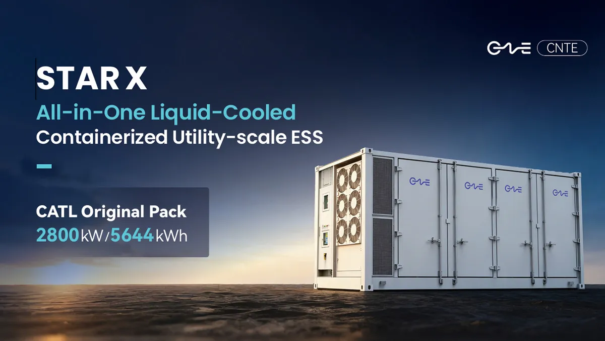
CNTE Launches STAR X Liquid-Cooled DC/AC Integrated Energy Storage System at Intersolar Europe 2026
Jul 06, 2026 -
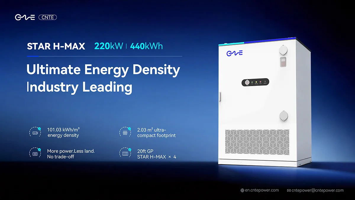
CNTE Unveils New STAR H-MAX Liquid-Cooled C&I ESS at Intersolar Europe 2026
Jun 23, 2026 -
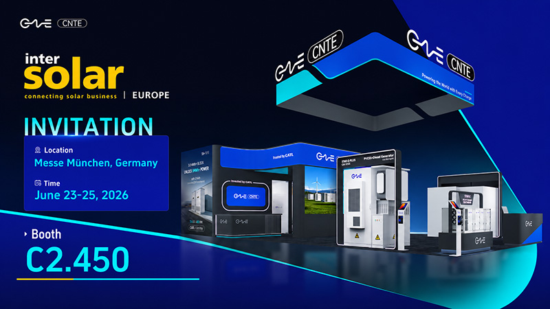
CNTE to Participate in Intersolar Europe 2026
May 20, 2026 -
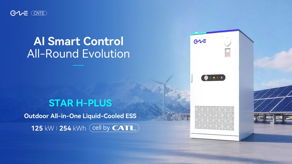
CNTE at KEY ENERGY 2026: Showcases STAR H-PLUS Outdoor Liquid-Cooled Energy Storage System
Mar 05, 2026 -

CNTE Honored as 2025 Forbes China Leading Global Brand
Jul 06, 2026 -

CNTE & YOU.ON Partner to Expand Storage Markets
May 19, 2025 -

CNTE Unveils Energy Storage Lineup at Solartech 2025
May 19, 2025 -
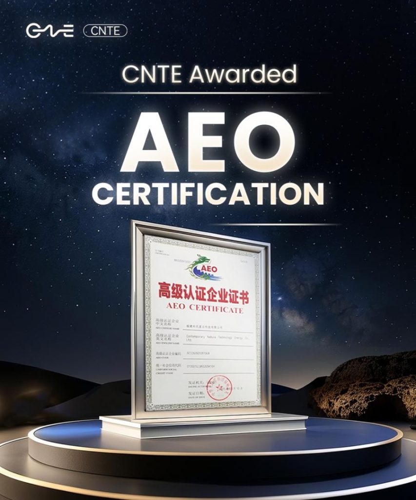
CNTE awarded AEO certification
Jul 06, 2026 -
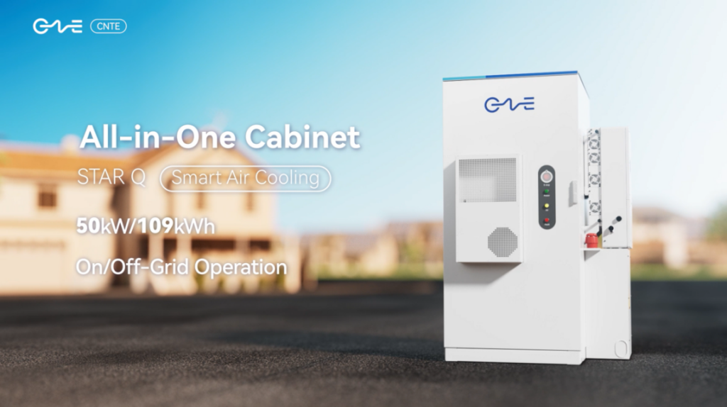
CNTE New Product Launch STAR Q
Jan 15, 2025
