
Improving Lifecycle Performance in Energy Storage Systems with LFP Battery CATL Integration
Large-scale energy storage relies on reliable electrochemistry to support grid stability, commercial peak shaving, and renewable energy integration. The adoption of lithium iron phosphate (LiFePO4) chemistry has grown significantly due to its chemical stability, prolonged cycle life, and thermal tolerance. In this sector, the lfp battery catl platform represents a widely adopted standard for stationary storage applications. Contemporary Nebula Technology Energy Co., Ltd. (CNTE) leverages these electrochemical cells to design integrated energy storage systems (ESS) that meet demanding industrial specifications.
Developing high-capacity battery systems requires an understanding of how individual cells behave under continuous cycling. By focusing on cell-to-pack engineering and thermal management, system integrators can maximize the performance of these cells. This analysis explores the system-level design, performance parameters, and integration practices required to deploy these technologies in utility and commercial settings.
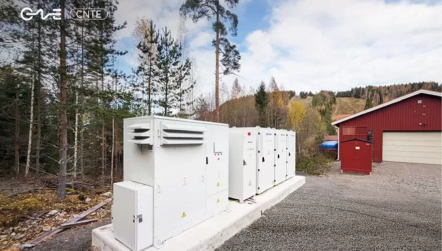
Electrochemical Characteristics of LFP Battery CATL Cells
The core chemistry of the lfp battery catl product line relies on an olivine crystal structure. Unlike nickel-manganese-cobalt (NMC) formulations, the phosphorus-oxygen bonds within the LiFePO4 cathode are covalent and highly stable. This molecular arrangement prevents oxygen release at elevated temperatures, reducing the likelihood of thermal runaway. The thermal runaway temperature for these cells sits above 270 degrees Celsius, providing a stable foundation for high-energy installations.
To meet the demands of utility-scale storage, cell capacities have shifted from the standard 280Ah format to larger 306Ah and 314Ah capacities. This increase in capacity is achieved without modifying the physical footprint of the cell container, resulting in a higher volumetric energy density at the pack level. The engineering behind these high-capacity cells involves several structural elements:
Anode Surface Engineering: Implementing graphite anodes with artificial coating technologies helps control the growth of the solid electrolyte interphase (SEI) layer. This minimizes active lithium consumption over thousands of charge-discharge cycles.
Electrolyte Formulations: Utilizing low-viscosity, high-conductivity electrolytes improves low-temperature lithium-ion transport and reduces internal resistance.
Cell-to-Pack (CTP) Architecture: By eliminating traditional modular enclosures, cells are integrated directly into the system container. This reduces structural weight and increases the space utilization efficiency inside the storage cabinet.
These features translate to long-term operational endurance. Under controlled charging rates, these cells are rated for over 6,000 to 8,000 cycles at an 80% depth of discharge (DoD) before the remaining capacity drops to 80% of its nominal value. This makes the technology suitable for heavy-use applications like daily peak shaving and frequency regulation.
Integrating LFP Battery CATL Cells into CNTE Storage Solutions
Integrating high-capacity cells into functional multi-megawatt systems requires addressing thermodynamic and electrical challenges. CNTE designs and manufactures energy storage systems that incorporate lfp battery catl units, pairing them with advanced liquid-cooling mechanisms and multi-tier monitoring architectures. The objective is to maintain uniform operating conditions across all series and parallel configurations.
Temperature distribution directly influences cell degradation rates. If one section of a battery rack operates at a temperature five degrees Celsius higher than another, the warmer cells will age faster. This imbalance leads to capacity mismatch, reducing the usable energy capacity of the entire system. To prevent this, CNTE utilizes active liquid cooling paths that route a water-glycol mixture through plates positioned directly beneath or between the cells. This method limits cell-to-cell temperature variations to less than three degrees Celsius across the entire containerized system.
Electrical safety is maintained through a structured battery management system (BMS) hierarchy. CNTE systems use a three-level BMS architecture designed to monitor and manage operations:
Battery Module Unit (BMU): Measures individual cell voltage and local temperatures, balancing cells passively to maintain voltage uniformity.
Cluster Battery Management System (CBMS): Aggregates data from multiple BMUs, monitors string currents, and manages isolation detection.
Group Battery Management System (GBMS): Interfaces with the power conversion system (PCS) and energy management system (EMS), coordinating system-level protection and communication protocols.
This multi-tiered management framework allows the integration of high-density lfp battery catl cells into systems ranging from 100 kWh commercial cabinets to multi-megawatt utility installations. By controlling environmental and electrical variables, the system prevents localized stress and extends overall operating life.
Industrial Applications and Operational Performance
Commercial and industrial (C&I) energy consumers use energy storage systems to lower operational costs and secure power supply. The operational profile of lfp battery catl systems aligns with several demanding applications. Each use case places specific demands on the battery chemistry and system integration.
Peak shaving requires the system to store energy during off-peak hours and discharge it when demand charges peak. Because industrial demand peaks can be sharp and frequent, the storage system must handle rapid charging and discharging without overheating. The low internal resistance of the LFP cells ensures that energy loss during these transitions remains minimal, maintaining high round-trip efficiency.
Microgrid integration represents another primary application. In remote locations or facilities with unstable grid connections, CNTE systems provide islanding capabilities. The storage unit acts as a voltage source, stabilizing frequency and absorbing transient loads when switching between renewable generation sources and backup diesel generators. The rapid response time of the solid-state inverter paired with LFP chemistry allows the system to respond to load changes within milliseconds.
Co-locating energy storage with electric vehicle (EV) charging infrastructure is also a growing practice. Ultra-fast EV chargers generate sudden, heavy demands on local distribution transformers. By integrating an lfp battery catl storage array, the system acts as a buffer. It discharges during high-power charging sessions and recharges during idle periods, preventing utility demand penalties and stabilizing the local grid interface.
Lifecycle Economics and Efficiency Parameters
For B2B buyers, the decision to invest in energy storage relies on project economics and Levelized Cost of Storage (LCOS). LCOS evaluates the total cost of energy discharged over the life of the system, accounting for initial capital expenditure, operational costs, replacement costs, and charging energy costs. The long service life of the lfp battery catl cell structure is an important factor in reducing this metric.
Calendar life is as significant as cycle life in stationary storage applications. Even when idle, battery materials undergo gradual degradation. Advanced LFP cells exhibit low self-discharge rates and minimal capacity loss over time when stored at recommended states of charge (SoC). Under typical environmental conditions, these systems can achieve a calendar life exceeding 15 years, reducing the need for mid-project battery replacement.
System-level round-trip efficiency (RTE) is another performance indicator. RTE measures the ratio of energy retrieved from the storage system to the energy supplied during charging. While cell-level efficiency can exceed 95%, system-level efficiency is affected by auxiliary power consumption, such as liquid cooling pumps, HVAC systems, and BMS controllers. CNTE refines these auxiliary systems through variable-speed pump controllers and adaptive thermal logic, maintaining a system-level AC-to-AC round-trip efficiency of approximately 88% to 90%.
By minimizing energy losses in auxiliary systems, operators reduce the amount of electricity required to operate the thermal management systems. This directly increases project yields, accelerating payback periods for commercial enterprises and utility asset owners alike.
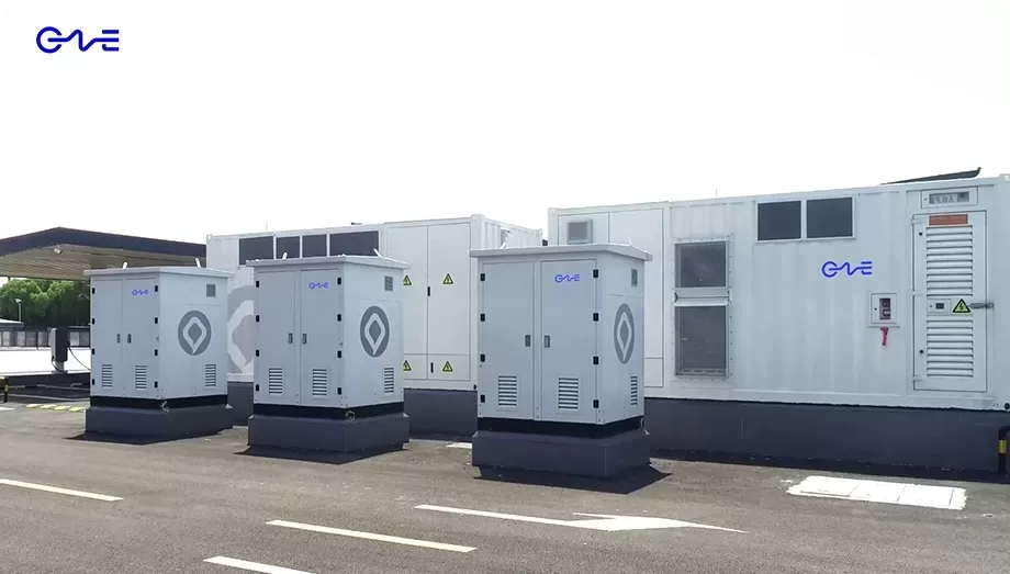
Custom Engineering and System Integration Services
No two industrial facilities share the exact same energy profile. Designing an effective energy storage solution requires evaluating load profiles, grid constraints, and local environmental conditions. CNTE provides complete engineering design services, using lfp battery catl technology as the foundation for custom energy storage architectures.
The design process begins with a detailed analysis of your facility's energy consumption data. Engineering teams simulate different sizing configurations to determine the optimal balance between battery capacity, power output, and system cost. This ensures the deployed system is sized correctly to deliver maximum financial return without unnecessary capital expenditure.
CNTE handles system integration from cell selection through to final commissioning. This includes structural containment design, liquid-cooling system calibration, and fire suppression integration. Each system is designed to comply with global standards, including UL9540A and IEC 62619, verifying that physical, thermal, and electrical safety measures are fully integrated into the enclosure design.
If you are planning an energy storage installation or need assistance transitioning your facility to a more resilient power architecture, contact our application engineering department. CNTE provides detailed project feasibility studies, system modeling, and engineering proposals tailored to your specific operational goals.
Frequently Asked Questions Regarding LFP Battery CATL Technology
Q1: What is the expected lifespan of a system utilizing lfp battery catl cells?
A1: Under typical commercial operating profiles, a system using these cells can operate for 12 to 15 years. The lifespan depends on variables such as the daily cycle rate, operating depth of discharge, and environmental temperature. Maintaining cell temperatures within the 20 to 30 degrees Celsius range helps maximize operational life.
Q2: Why is LFP chemistry preferred over NMC for commercial and industrial energy storage?
A2: Lithium iron phosphate chemistry offers superior thermal stability and a longer cycle life compared to nickel-manganese-cobalt chemistry. LFP cells do not contain cobalt, which simplifies supply chain sourcing. They also have a higher resistance to thermal runaway, which is a major design consideration for large-scale indoor and containerized installations.
Q3: How does liquid cooling compare to air cooling in lfp battery catl installations?
A3: Liquid cooling provides significantly higher heat transfer coefficients compared to air cooling. This allows the system to maintain uniform temperatures across all battery cells, preventing localized hot spots. While liquid cooling systems require auxiliary pumps and plumbing, the resulting improvement in temperature uniformity extends battery life and supports consistent performance under high-current charging conditions.
Q4: What standards do CNTE systems meet when integrating these battery cells?
A4: CNTE systems are engineered to meet strict international standards, including IEC 62619 for safety in industrial applications, UL 1973 for stationary battery packs, and UL 9540A for evaluating thermal runaway fire propagation. These certifications confirm that the integrated systems are suitable for utility connection and commercial deployment.
Q5: How does State of Charge (SoC) management prevent damage to the battery cells?
A5: The battery management system monitors voltage, current, and temperature to calculate the SoC of each cell. By preventing cells from overcharging (which can cause lithium plating) or over-discharging (which can lead to copper dissolution and internal short circuits), the BMS maintains the structural integrity of the cell electrodes over thousands of cycles.
Get in Touch
Recent Posts
-
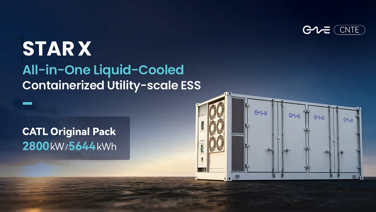
CNTE Launches STAR X Liquid-Cooled DC/AC Integrated Energy Storage System at Intersolar Europe 2026
Jul 06, 2026 -
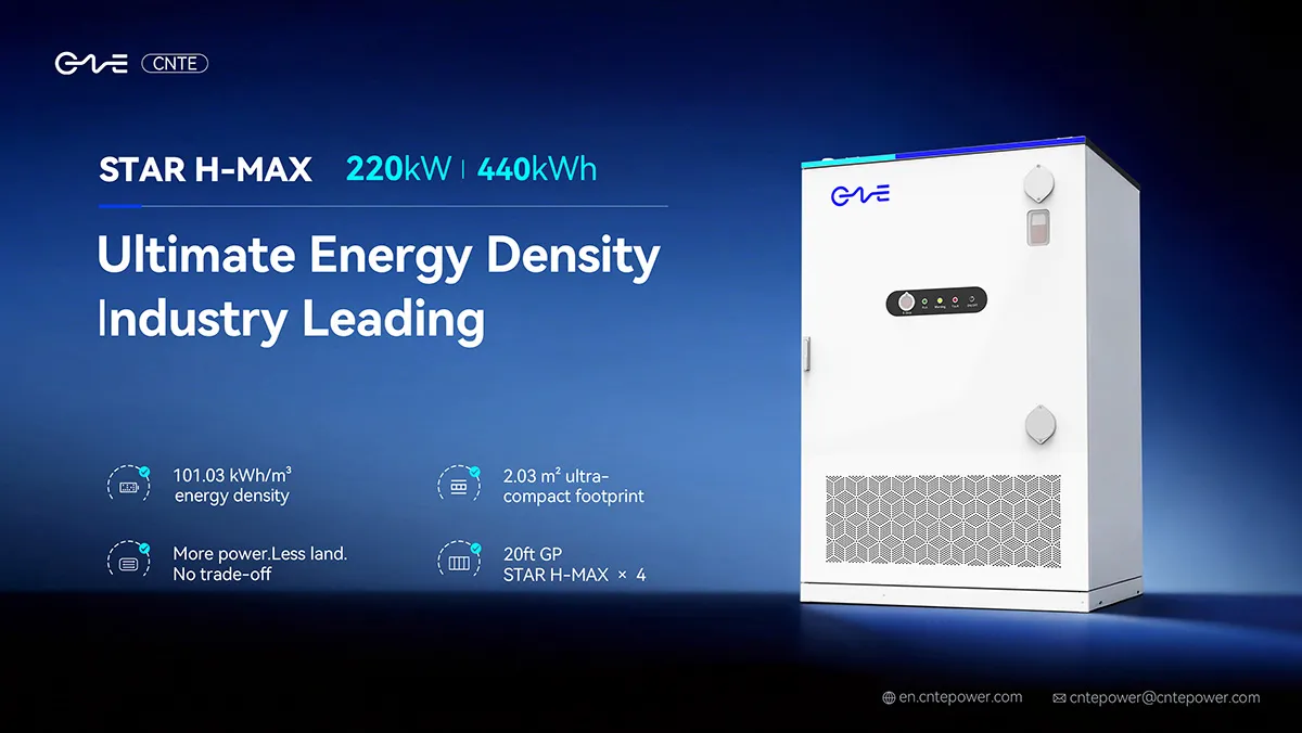
CNTE Unveils New STAR H-MAX Liquid-Cooled C&I ESS at Intersolar Europe 2026
Jun 23, 2026 -
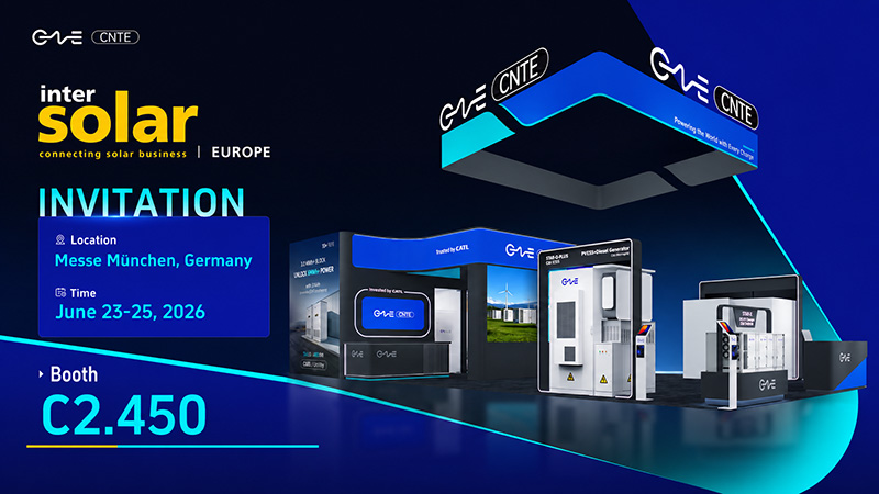
CNTE to Participate in Intersolar Europe 2026
May 20, 2026 -
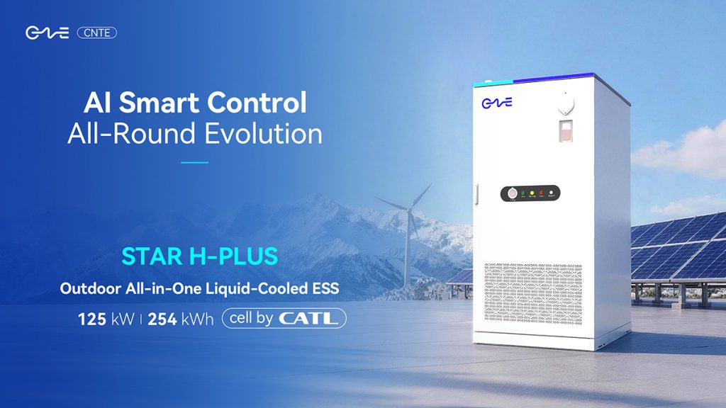
CNTE at KEY ENERGY 2026: Showcases STAR H-PLUS Outdoor Liquid-Cooled Energy Storage System
Mar 05, 2026 -

CNTE Honored as 2025 Forbes China Leading Global Brand
Jul 06, 2026 -

CNTE & YOU.ON Partner to Expand Storage Markets
May 19, 2025 -
CNTE Unveils Energy Storage Lineup at Solartech 2025
May 19, 2025 -
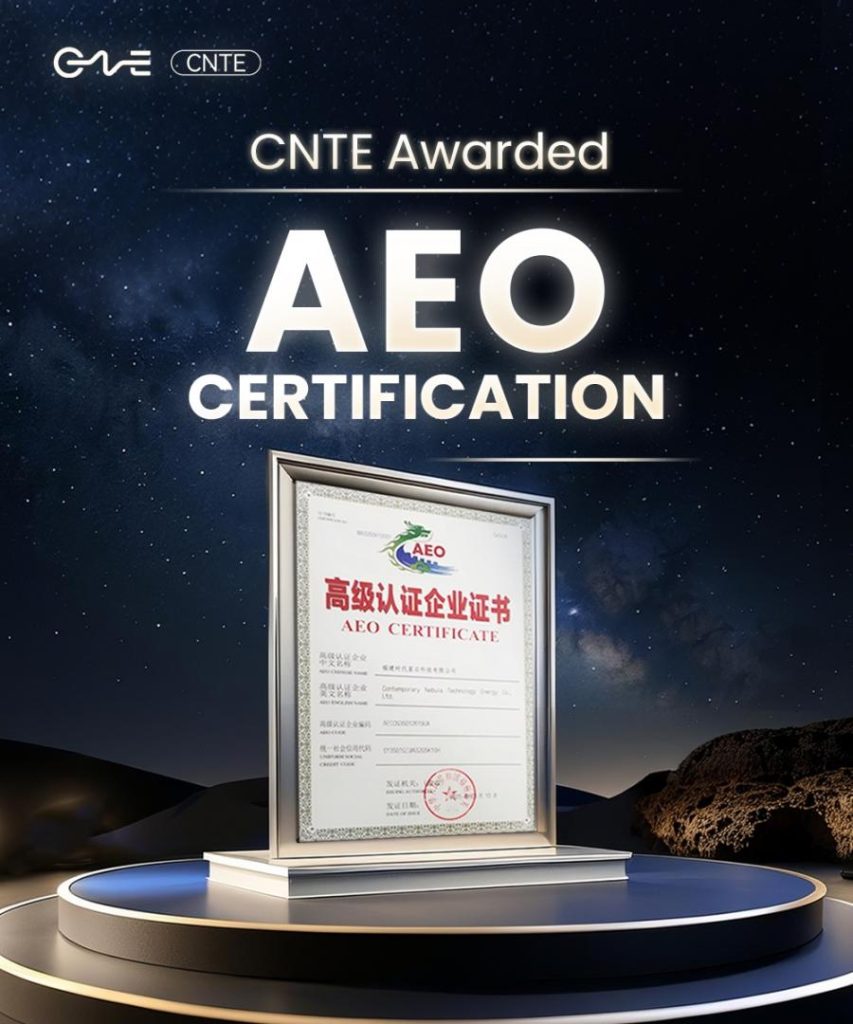
CNTE awarded AEO certification
Jul 06, 2026 -
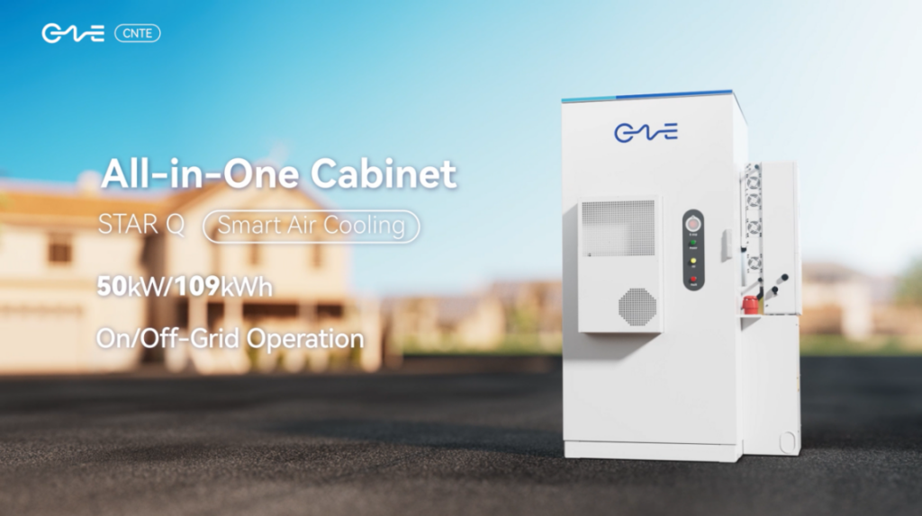
CNTE New Product Launch STAR Q
Jan 15, 2025 -
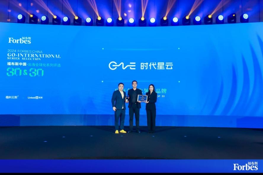
CNTE Named to Forbes China 2024 Top 30 Go-International Brands
Jul 06, 2026
