
5 Structural Innovations Inside the kirin battery catl System
Battery pack engineering heavily dictates the performance, range, and operational profile of electric power platforms and large-scale storage arrays. The transition from heavily modularized designs to Cell-to-Pack (CTP) configurations represents a fundamental shift in how engineers manage space and thermal loads. The third generation of this methodology, widely recognized through the kirin battery catl, completely re-engineers the internal layout of the power system. Removing the secondary module enclosures frees up significant physical space, allowing for more active materials to be packed into the exact same footprint. This specific design achieves a volume utilization rate of 72%, setting a distinct benchmark for volumetric efficiency in the industry. The design philosophy abandons traditional layered assembly in favor of a highly integrated, multi-functional internal structure.
Volumetric Efficiency and the Multi-Functional Elastic Interlayer
The foundation of this architecture lies in the consolidation of components. Legacy pack designs utilize separate physical layers for structural support, thermal insulation, and liquid cooling. These distinct components consume valuable millimeters within the battery enclosure. The kirin battery catl merges these three distinct functions into a single, multi-functional elastic interlayer.
This interlayer is positioned directly between individual cells. As lithium-ion cells undergo repeated charge and discharge cycles, the internal chemical reactions cause the physical dimensions of the cell to fluctuate. The anode expands as lithium ions intercalate into the graphite matrix. Traditional rigid pack enclosures struggle to accommodate this swelling, often leading to mechanical stress on the busbars and electrical connections. The elastic nature of the new interlayer acts as a continuous shock absorber. It accommodates the microscopic expansion and contraction of each cell while maintaining constant pressure across the cell face.
Maintaining uniform pressure ensures long-term cell health. Uneven pressure distribution can lead to localized lithium plating, accelerating internal degradation. The integrated interlayer guarantees that mechanical loads are evenly distributed along the longitudinal axis of the pack. The micro-bridge structure within this layer enhances the overall structural rigidity of the system, transforming the cooling components into active load-bearing members.
Advanced Thermodynamics and Inter-Cell Liquid Cooling
Heat generation remains the primary limiting factor for high-current applications. Rapid charging generates intense Joule heating within the internal resistance of the cell. Conventional thermal management systems place a flat liquid cooling plate at the very bottom of the battery tray. Heat must travel from the top of the cell, down through the internal jelly roll, across the cell casing, and finally into the cooling plate. This long thermal pathway creates steep temperature gradients within the cell itself.
The engineering approach within the kirin battery catl relocates the liquid cooling plates from the bottom of the pack to the wide lateral faces of the cells. Placing the cooling channels between adjacent cells quadruples the heat exchange surface area. Heat is drawn directly out of the largest surface of the prismatic cell, drastically shortening the thermal pathway.
This precise thermodynamic control enables charging rates of up to 5C. The system dissipates heat fast enough to allow the cells to accept massive electrical currents without exceeding safe operational temperature thresholds. The inter-cell cooling design acts as a physical thermal barrier. If a single cell experiences an internal short circuit and begins generating excessive heat, the liquid cooling plates immediately extract that thermal energy, stopping the heat from transferring to adjacent cells and maintaining the integrity of the entire array.
Fluid dynamics play a major role in this cooling efficiency. The internal micro-channels within the vertical cooling plates are designed to maintain a uniform flow rate of the glycol-water coolant mixture. Uniform flow ensures that the temperature differential across the entire battery pack remains within a tight margin of fewer than 3 degrees Celsius, preventing localized hot spots that deteriorate the Solid Electrolyte Interphase (SEI) layer over time.
Chemistry Agnostic Integration: NMC and LFP Capabilities
Structural efficiency benefits all battery chemistries, regardless of the active materials used inside the cathode. The architecture accommodates both Nickel Manganese Cobalt (NMC) and Lithium Iron Phosphate (LFP) cells.
NMC chemistry provides a higher inherent specific energy. When integrated into this highly efficient CTP 3.0 structure, the overall system energy density reaches 255 Wh/kg. This density directly translates to extended operational durations for high-demand applications, providing maximum energy storage within a strictly confined mass limit.
LFP chemistry offers superior thermal stability and a longer cycle life, but traditionally suffers from a lower volumetric and gravimetric density. The kirin battery catl structure compensates for the lower inherent density of LFP by maximizing the sheer volume of active material packed into the space. LFP configurations utilizing this architecture achieve 160 Wh/kg. This engineering feat expands the viability of LFP into applications that previously required the higher density of NMC, offering a highly economical and durable alternative without severe spatial penalties.
Spatial Efficiency in C&I and Utility-Scale Deployments
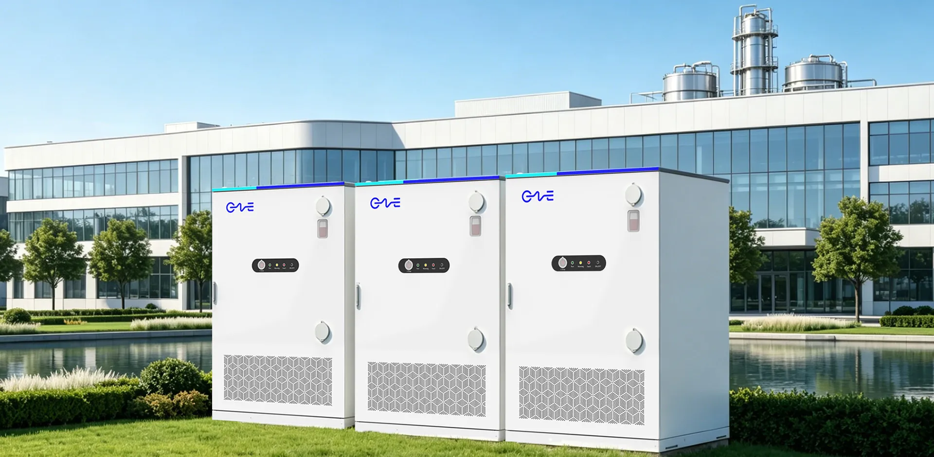
The principles driving modern pack design share direct parallels with stationary energy storage requirements. Commercial and Industrial (C&I) facilities, alongside utility-scale solar farms, require massive amounts of energy storage housed within standard shipping containers or compact outdoor cabinets. Space acts as a premium commodity on commercial real estate.
Applying high-density CTP engineering principles to stationary storage transforms project economics. Maximizing the volume utilization within a standard 20-foot container allows developers to deploy higher megawatt-hour (MWh) capacities without expanding the physical footprint of the installation. High-density packing reduces land acquisition costs, foundation pouring requirements, and overall balance of plant (BOP) expenditures.
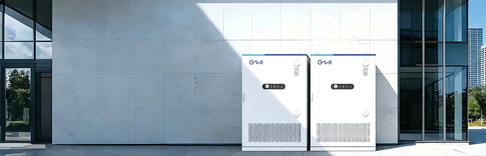
Commercial facilities face steep utility demand charges based on their 15-minute peak power draw. Deploying high-density storage systems in tight basement electrical rooms or crowded loading docks allows facility managers to shave these peaks effectively. Managing the thermal output of thousands of tightly packed cells requires sophisticated engineering.
CNTE (Contemporary Nebula Technology Energy Co., Ltd.) specializes in developing all-scenario energy storage solutions that leverage advanced thermal and structural integration. By utilizing comprehensive liquid-cooling architectures similar in concept to modern high-density automotive packs, CNTE (Contemporary Nebula Technology Energy Co., Ltd.) ensures that stationary storage systems maintain strict temperature uniformity across the entire container. This precise thermal management extends the overall cycle life of the storage asset, ensuring stable operation during demanding peak-shaving and frequency regulation applications.
Enhancing Assembly Line Economics and System Rigidity
Manufacturing large-scale battery packs involves highly complex assembly lines. Traditional systems require robots to assemble cells into modules, weld module connections, place modules into battery trays, and route extensive wiring harnesses. Every module requires its own end plates, side plates, and structural fasteners.
The kirin battery catl design significantly simplifies this manufacturing process. Eliminating the intermediate module stage reduces the total part count of the battery pack. Fewer components translate directly to a streamlined supply chain, reduced inventory management overhead, and faster assembly line throughput. The reduction in physical parts also decreases the number of mechanical fastening steps, heavily relying instead on advanced structural adhesives.
The structural integrity of the final pack does not rely on heavy aluminum module housings. The integrated cooling plates and elastic interlayers form a unified structural matrix. Once the cells and interlayers are compressed and sealed within the pack enclosure, the entire assembly behaves as a single, rigid composite material. This z-axis load-bearing architecture provides exceptional resistance to vibration and mechanical shock. The pack easily meets rigorous transportation standards and maintains an IP68 rating against moisture and dust ingress, as the simplified structure allows for more robust perimeter sealing.
Internal electrical routing undergoes a similar simplification. The removal of module boundaries allows engineers to utilize streamlined Flexible Printed Circuits (FPCs) or even wireless Battery Management System (BMS) nodes, further reducing the weight and complexity of copper wiring harnesses running through the pack.
Frequently Asked Questions (FAQ)
Q1: What defines the Cell-to-Pack (CTP) 3.0
architecture?
A1: CTP 3.0 represents a design methodology where
individual battery cells are integrated directly into the main pack enclosure.
This approach completely bypasses the traditional intermediate step of grouping
cells into smaller, rigid modules, eliminating redundant structural materials
and increasing the volume available for active energy-storing components.
Q2: How does the cooling system differ from legacy battery pack
designs?
A2: Legacy designs typically feature a single liquid
cooling plate situated at the bottom of the battery tray. The newer architecture
inserts active liquid cooling plates vertically between the lateral faces of
adjacent cells. This arrangement increases the total heat exchange surface area
by four times, enabling much faster heat extraction during high-current
operations.
Q3: Can this structural design accommodate different cathode
chemistries?
A3: Yes, the physical architecture is entirely
chemistry-agnostic. It houses Nickel Manganese Cobalt (NMC) cells for maximum
energy density, achieving up to 255 Wh/kg, or Lithium Iron Phosphate (LFP) cells
for enhanced cycle life and economy, reaching 160 Wh/kg.
Q4: How does the system handle the physical expansion of cells during
charging?
A4: The design incorporates a multi-functional elastic
interlayer positioned between the cells. This layer continuously compresses and
expands, absorbing the microscopic volumetric changes of the cells during their
charge and discharge cycles, preventing mechanical stress from damaging the
electrical busbar connections.
Q5: Does removing the module enclosures reduce the physical strength
of the battery pack?
A5: The structural strength increases under
this design. The liquid cooling plates and the elastic interlayers are bonded to
the cells, creating a unified micro-bridge structure. The entire internal
assembly functions as a singular load-bearing matrix, providing superior z-axis
strength and high resistance to mechanical shock and vibration.
Inquiry
For detailed engineering specifications, project sizing, and procurement pricing regarding high-density, all-scenario energy storage systems, please submit your requirements to the engineering team at CNTE (Contemporary Nebula Technology Energy Co., Ltd.).
Get in Touch
Recent Posts
-
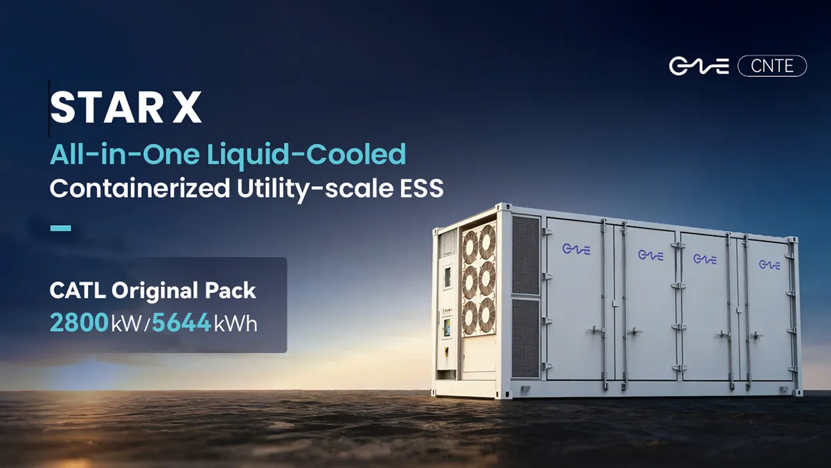
CNTE Launches STAR X Liquid-Cooled DC/AC Integrated Energy Storage System at Intersolar Europe 2026
Jul 06, 2026 -
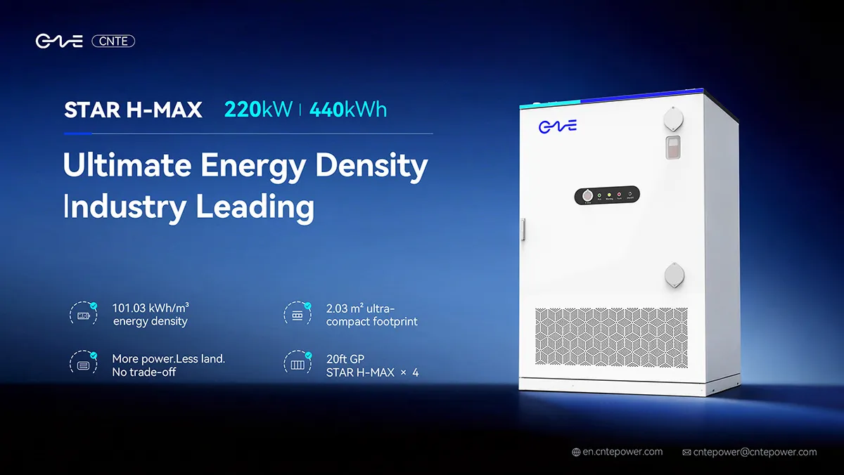
CNTE Unveils New STAR H-MAX Liquid-Cooled C&I ESS at Intersolar Europe 2026
Jun 23, 2026 -
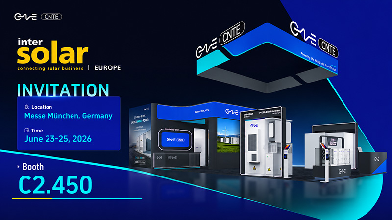
CNTE to Participate in Intersolar Europe 2026
May 20, 2026 -
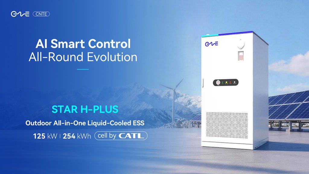
CNTE at KEY ENERGY 2026: Showcases STAR H-PLUS Outdoor Liquid-Cooled Energy Storage System
Mar 05, 2026 -

CNTE Honored as 2025 Forbes China Leading Global Brand
Jul 06, 2026 -
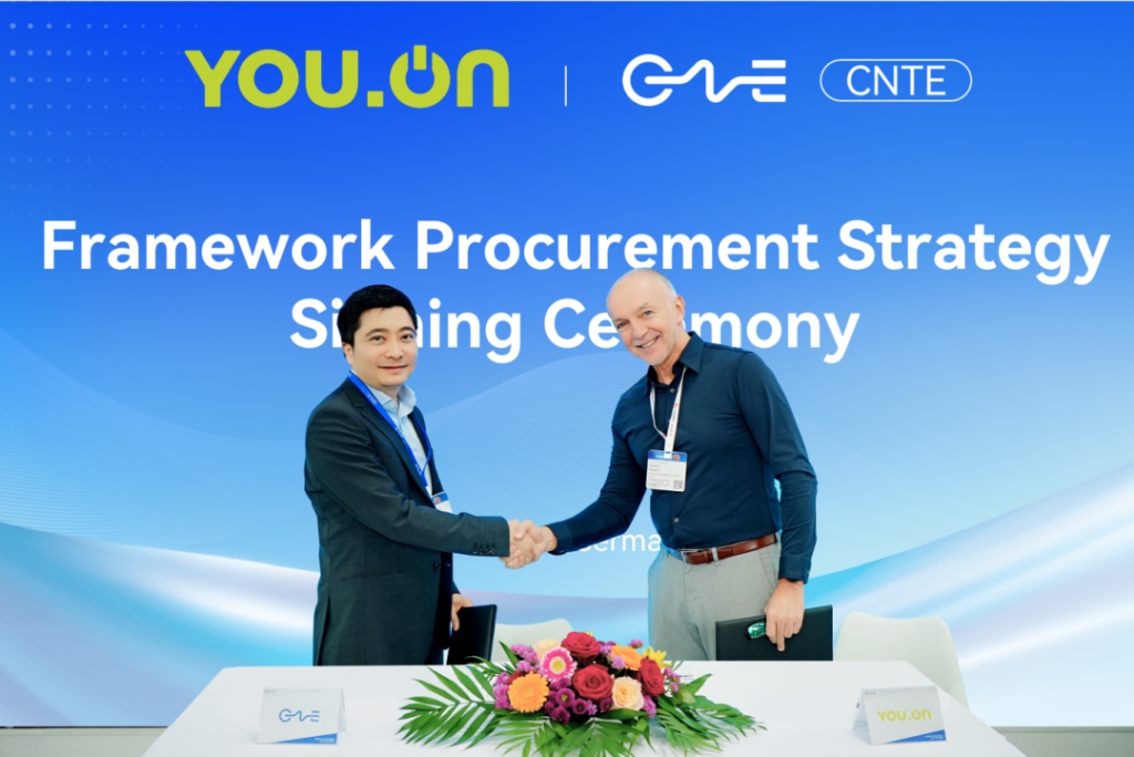
CNTE & YOU.ON Partner to Expand Storage Markets
May 19, 2025 -
CNTE Unveils Energy Storage Lineup at Solartech 2025
May 19, 2025 -
CNTE awarded AEO certification
Jul 06, 2026 -
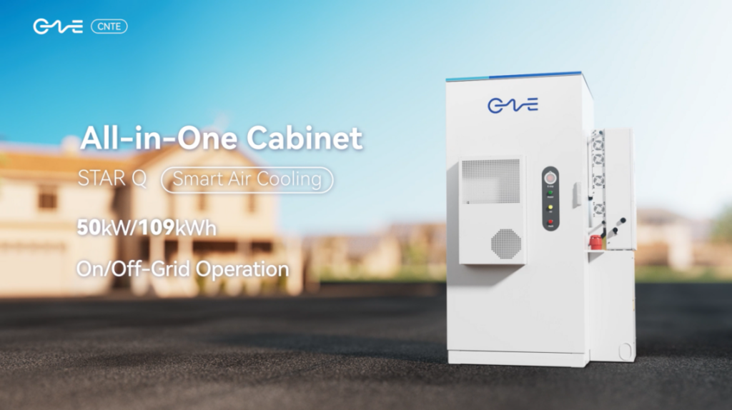
CNTE New Product Launch STAR Q
Jan 15, 2025 -
CNTE Named to Forbes China 2024 Top 30 Go-International Brands
Jul 06, 2026
