
How Do Solutions Solar Batteries Stabilize Modern Commercial Power Grids?
The global transition toward high-penetration renewable energy grids presents structural challenges to power system stability. Solar photovoltaic generation is inherently variable, subject to atmospheric fluctuations and diurnal solar irradiance cycles. As utility providers and commercial enterprises scale up solar generation, the mismatch between peak production windows and facility consumption profiles creates severe grid stress, localized voltage instability, and curtailment issues. Addressing these operational imbalances demands robust solutions solar batteries capable of buffering intermittency, maintaining frequency stability, and firming power output.
Energy storage platforms have transitioned from simple backup reserve units into sophisticated, multi-layered power generation assets. Advanced system architectures pioneered by global leaders such as CNTE (Contemporary Nebula Technology Energy Co., Ltd.) have transformed stationary storage into grid-supportive infrastructure. Evaluating these systems requires examining electrical topologies, thermal management physics, chemical stability, and software-driven dispatching strategies capable of delivering long lifetime value.
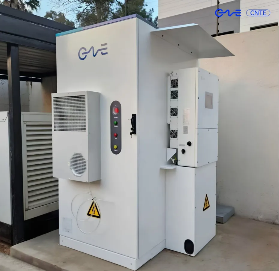
System Topologies: AC-Coupled vs. DC-Coupled Architectures
Designing an industrial energy storage facility begins with selecting the appropriate electrical coupling architecture. The decision between Direct Current (DC) and Alternating Current (AC) coupling dictates system conversion efficiency, capital expenditure, installation complexity, and operational flexibility.
DC-Coupled System Architectures
In a DC-coupled configuration, the solar PV array and the battery energy storage system (BESS) share a common DC bus behind a shared central power conversion system (PCS). Solar generation routes directly through high-efficiency Maximum Power Point Tracking (MPPT) charge controllers to charge the battery bank without undergoing AC conversion steps.
Conversion Efficiency: By avoiding double conversion (DC to AC and back to DC), round-trip efficiency during solar charging cycles improves by 2% to 4%.
BOS Reduction: Shared inverter hardware reduces total balance-of-system costs, footprint requirements, and cabling overhead.
Clipping Recapture: Excess solar output that exceeds the AC inverter capacity (inverter clipping) can be redirected directly into the battery, salvaging energy that would otherwise be curtailed.
AC-Coupled System Architectures
AC-coupled systems isolate the PV generation plant and the battery storage plant onto distinct AC connection points. Each system operates dedicated inverters, combining outputs at the facility distribution board or high-voltage transformer substations.
Retrofit Versatility: AC coupling provides an adaptable pathway for adding storage to existing commercial solar installations without modifying installed solar inverter infrastructure.
Redundancy and Reliability: Independent inverter topology isolates faults. A failure in the solar inverter pipeline does not compromise the dispatch capability of the storage system.
Expanded Dispatch Control: AC systems allow simultaneous full-capacity charging from the grid while solar arrays deliver maximum output directly to site loads.
Cell Chemistry and Thermal Physics Engineering
At the core of industrial storage assets is electrochemical cell chemistry. While nickel manganese cobalt (NMC) formulations historically dominated mobile applications due to energy density, stationary commercial installations rely almost exclusively on Lithium Iron Phosphate (LFP) chemistry.
LFP chemistry offers intrinsic structural stability. The covalent phosphorus-oxygen bonds inside the olivine crystal lattice withstand high temperature thresholds without undergoing mechanical breakdown. This chemical structure prevents oxygen release under thermal stress, mitigating combustion propagation within system modules.
Cell lifecycles are dictated by operating temperature, current discharge rate (C-rate), and depth of discharge (DoD). Operating a cell consistently above 35°C accelerates solid-electrolyte interphase (SEI) layer growth, accelerating lithium inventory loss and internal resistance increases. Consequently, thermal management design serves as the primary engineering factor determining asset longevity.
Thermal Management: Air Cooling versus Liquid Cooling
Traditional forced-air HVAC systems pull ambient air through battery racks. Air cooling creates non-uniform temperature distribution inside container enclosures, resulting in temperature variances up to 8°C between center cells and peripheral modules. Micro-climatic variance causes uneven aging across cell series strings, reducing useful system capacity to the performance level of the lowest-performing cell.
Advanced liquid-cooled systems developed by companies like CNTE maintain tight temperature uniformity across thousands of individual cells. Circulating dynamic liquid glycol coolant through micro-channel cold plates directly in contact with cell faces maintains internal module variations under 2.5°C. This precise thermal regulation yields distinct operational advantages:
Extended cycle lifetime exceeding 8,000 cycles at 80% Depth of Discharge.
Reduced auxiliary power consumption compared to high-volume air compressors.
Higher energy density design, reducing container footprint requirements on site by up to 35%.
IP65 ingress protection seals cell assemblies away from ambient dust, humidity, and corrosive atmospheric pollutants.
Strategic Deployment Modes for Grid-Tied Solutions Solar Batteries
Commercial energy storage installations deliver financial returns through application stacking—executing multiple grid-support actions simultaneously or sequentially through automated controls.
1. Peak Shaving and Demand Charge Management
Industrial facilities face substantial billing penalties based on peak power draw (kW) measured during 15-minute operational windows. System controllers continuously track site load meters. When facility demand breaches designated thresholds, the storage system instantaneously discharges energy to supply localized loads, capping grid power intake and reducing demand charges.
2. Time-of-Use (ToU) Energy Arbitrage
Electricity markets operate on dynamic pricing structures where energy tariffs rise during peak evening periods. Modern energy storage systems store excess mid-day solar generation or low-cost off-peak grid electricity, subsequently discharging that stored energy during high-tariff operational windows to maximize monetary savings.
3. Renewable Capacity Firming and Ramp-Rate Control
Passing cloud cover can cause sudden solar PV output drops exceeding 70% in seconds. Grid operators mandate strict ramp-rate limits to maintain distribution voltage stability. Storage systems monitor solar generation at sub-second intervals, immediately injecting power to smooth output profiles and fulfill utility power purchase agreement (PPA) ramp specifications.
4. Ancillary Services: Frequency Regulation and Spinning Reserve
Grid frequency must strictly maintain 50Hz or 60Hz baselines. Industrial BESS assets offer millisecond-level response times, automatically absorbing power during over-frequency events or injecting power during under-frequency events. Participating in automated frequency response markets provides high-value operational revenue streams.
Commercial Criteria for Evaluating Large-Scale Energy Storage Projects
Engineering procurement teams must evaluate energy storage investments using technical baseline criteria rather than relying on initial capital expenditure figures alone. Total cost of ownership depends on long-term performance retention metrics.
Levelized Cost of Storage (LCOS) Calculation Framework
LCOS measures the total lifetime cost of moving an energy unit through a storage device. LCOS calculations integrate upfront equipment costs, balance-of-plant civil work, replacement schedules, auxiliary HVAC power losses, and total delivered megawatt-hours across the operational lifecycle.
LCOS is governed by three primary physical variables:
Round-Trip Efficiency (RTE): The ratio of energy delivered during discharge relative to energy consumed during charge. Utility-grade LFP systems maintain system-level RTE between 85% and 90%, accounting for conversion and cooling losses.
Degradation Rate and End-of-Life (EoL) Horizon: Batteries are considered past EoL when maximum usable capacity declines to 70% of initial nameplate rating. High-grade systems utilize active BMS balancing to slow down degradation trajectories.
C-Rate Operational Profiles: High continuous charge and discharge rates accelerate mechanical cell strain. Designing modular configurations that run at fractional C-rates (e.g., 0.5C charging) extends cell structural integrity.
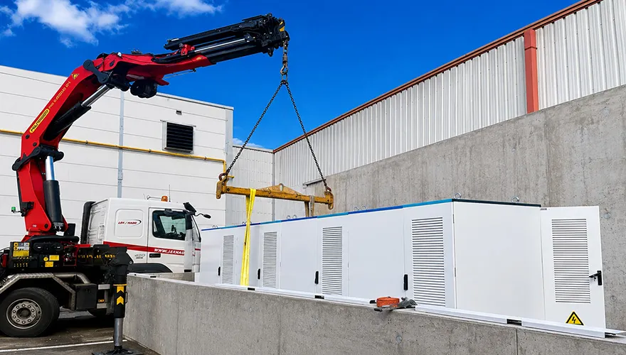
Integrating Energy Management Systems (EMS) with Variable Photovoltaic Output
Hardware capability relies entirely on intelligent control software. The Energy Management System (EMS) acts as the operational brain, coordinating interactions between cell-level Battery Management Systems (BMS), site Power Conversion Systems (PCS), facility loads, and regional grid operators.
Advanced software architectures incorporate predictive machine learning models to optimize system dispatch schedules automatically. Algorithms process real-time variables including historical facility load curves, site solar generation forecasts, ambient temperature forecasts, and dynamic wholesale market clearing prices.
Using predictive analytics, modern solutions solar batteries enable dynamic response protocols. If software models predict high solar irradiance combined with low building load during mid-day, the system reserves cell capacity to absorb solar generation. Conversely, if high ambient temperatures are forecasted to trigger high cooling loads and elevated demand charges later in the day, the system pre-charges during early morning off-peak hours.
Hardware and Software Integration Standards
Deploying storage equipment within modern utility grids requires strict compliance with international safety, interoperability, and cybersecurity frameworks. Equipment selection must align with established standards to facilitate grid interconnection approvals.
Safety Certification Frameworks: UL 9540 and UL 9540A test methods quantify thermal run-away propagation behavior across individual cells, modules, and full unit enclosures, proving containment efficacy without active fire suppression intervention.
Electrical Safety Compliance: IEC 62619 and UL 1973 validate cell and pack level electrical, mechanical, and environmental endurance under severe operational stress.
Interconnection Governance: IEEE 1547 and California Rule 21 standards define smart inverter behaviors, specifying mandatory anti-islanding protection, reactive power support, voltage ride-through performance, and real-time power modulation.
Telemetry Protocols: High-performance hardware platforms from providers like CNTE offer seamless integration with high-voltage utility grids through standard industrial protocols, including Modbus TCP, DNP3, and IEC 61850.
Frequently Asked Questions
Q1: What is the expected service lifecycle of a commercial lithium
iron phosphate (LFP) solar battery system?
A1: A commercial LFP
system typically achieves an operational lifespan ranging between 10 to 15
years, corresponding to 6,000 to 10,000 equivalent full charge-discharge cycles
under standard operating temperatures (25°C) and managed charge rates (0.5C).
System longevity depends directly on thermal management efficiency, depth of
discharge limits, and precise state-of-charge balancing.
Q2: How does liquid cooling technology compare to traditional
forced-air HVAC cooling in utility energy storage containers?
A2:
Liquid cooling transfers heat via liquid heat exchangers directly in contact
with battery cells, providing up to 50 times higher heat transfer efficiency
than air. Liquid systems keep intra-container temperature variations within
2.5°C, compared to 8°C variations in air-cooled systems. This reduces parasitic
cooling power demand, preserves usable capacity, and extends system cycle
life.
Q3: What is the primary difference between AC-coupled and DC-coupled
energy storage architectures?
A3: In DC-coupled systems, solar
panels and storage systems connect directly to a shared DC bus managed by a
central inverter, maximizing efficiency for newly built integrated
solar-plus-storage projects. AC-coupled systems connect solar and battery
storage systems independently on the AC side of the electrical distribution
network, making them ideal for retrofitting existing operational solar PV
installations.
Q4: Why is active cell balancing important in high-voltage industrial
battery systems?
A4: Industrial battery strings connect hundreds of
cells in series to achieve high operational voltages. Minor manufacturing
tolerances create differences in capacity and internal resistance across cells.
Active balancing redistribution circuits transfer charge from higher-voltage
cells to lower-voltage cells during operation, ensuring all cells charge and
discharge uniformly, preventing premature string shutdown.
Q5: What safety standards must commercial battery storage systems
meet to gain utility grid connection approval?
A5: Systems must
comply with key safety and operational standards including UL 9540 (system
safety), UL 9540A (thermal runaway propagation testing), IEC 62619 (industrial
lithium cell safety), and IEEE 1547 / California Rule 21 (grid interconnection
performance and smart inverter functionality).
Initiate Your Industrial Energy Storage Project
Selecting appropriate grid-scale energy storage hardware requires rigorous engineering analysis, customized electrical sizing, and deep thermal evaluation. Engineering tailored solutions solar batteries for utility and industrial applications demands hardware built to withstand rigorous continuous cycling under harsh environmental conditions.
Contact the application engineering team at CNTE to discuss technical specifications, system sizing analysis, and custom containerized BESS configurations for your upcoming commercial or utility-scale project. Submit your Project Requirements and Technical RFQs today.
Get in Touch
Recent Posts
-
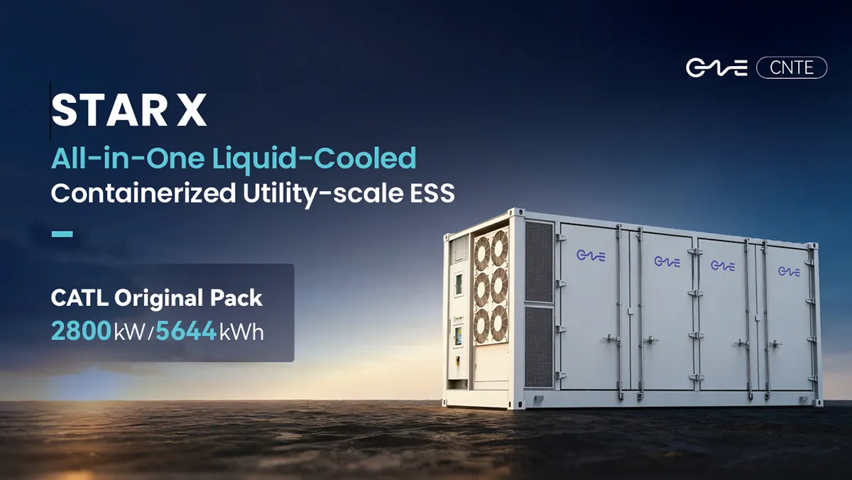
CNTE Launches STAR X Liquid-Cooled DC/AC Integrated Energy Storage System at Intersolar Europe 2026
Jul 06, 2026 -
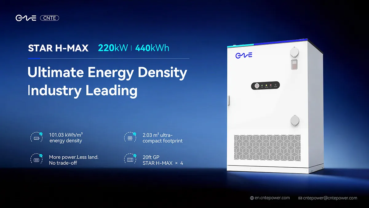
CNTE Unveils New STAR H-MAX Liquid-Cooled C&I ESS at Intersolar Europe 2026
Jun 23, 2026 -
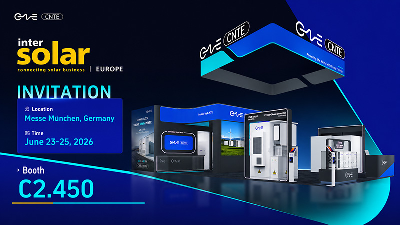
CNTE to Participate in Intersolar Europe 2026
May 20, 2026 -
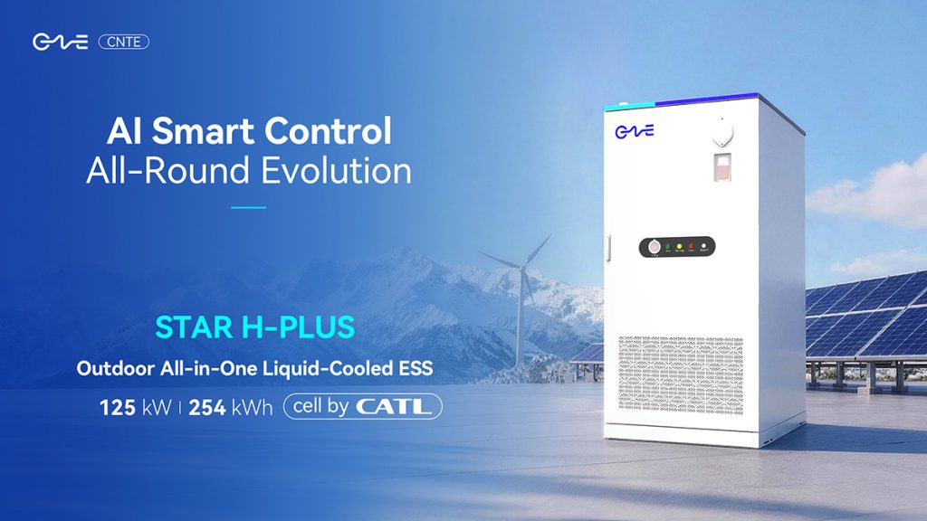
CNTE at KEY ENERGY 2026: Showcases STAR H-PLUS Outdoor Liquid-Cooled Energy Storage System
Mar 05, 2026 -

CNTE Honored as 2025 Forbes China Leading Global Brand
Jul 06, 2026 -
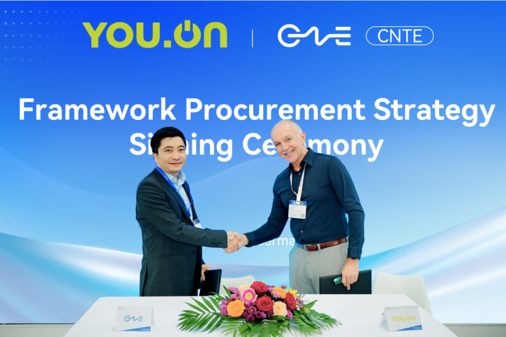
CNTE & YOU.ON Partner to Expand Storage Markets
May 19, 2025 -

CNTE Unveils Energy Storage Lineup at Solartech 2025
May 19, 2025 -
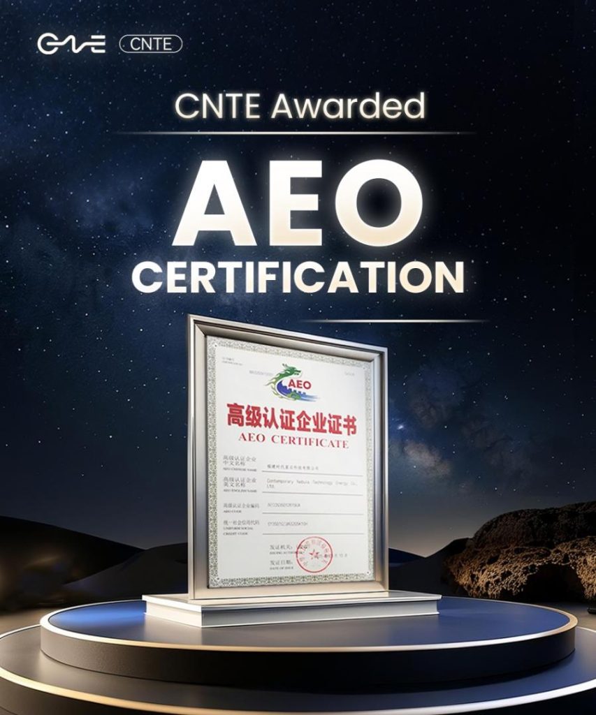
CNTE awarded AEO certification
Jul 06, 2026 -
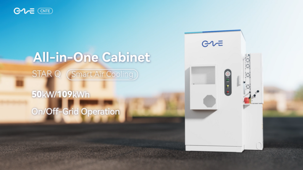
CNTE New Product Launch STAR Q
Jan 15, 2025 -
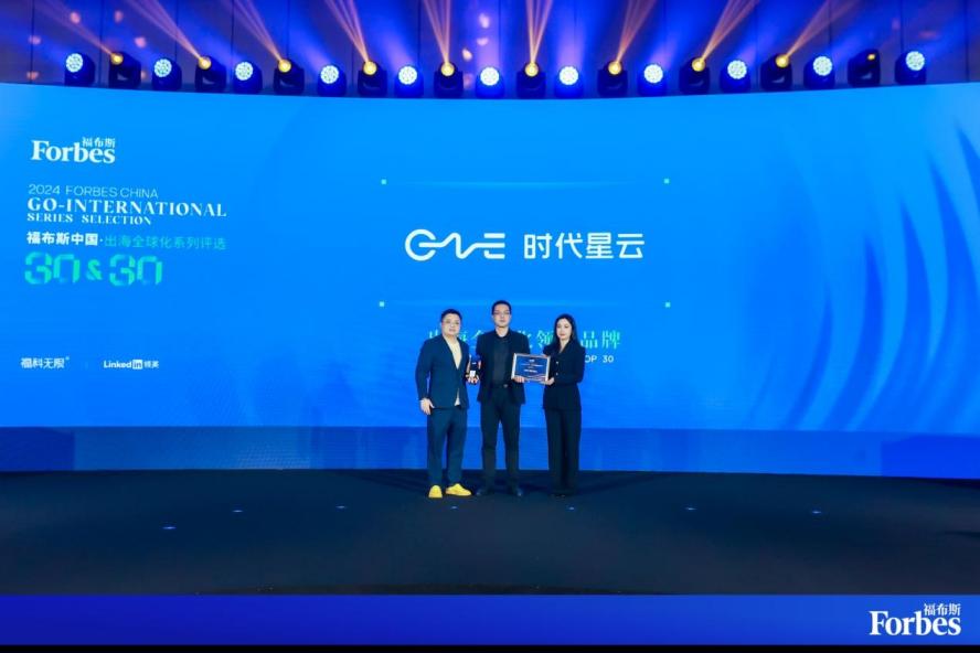
CNTE Named to Forbes China 2024 Top 30 Go-International Brands
Jul 06, 2026
