
Engineering Grid Resilience: The Technical and Commercial Guide to a BESS System for Solar
Solar photovoltaic (PV) generation exhibits high output capacity during midday peak solar irradiance, but its inherent output variability creates systemic challenges for electrical grid stability—a dynamic often illustrated by the energy sector's "duck curve." Deploying a robust bess system for solar bridges the critical operational gap between intermittent generation and continuous load demand. By integrating battery energy storage systems (BESS) directly with solar infrastructure, utility operators, independent power producers (IPPs), and commercial facilities transform non-dispatchable solar generation into flexible, high-value power assets.
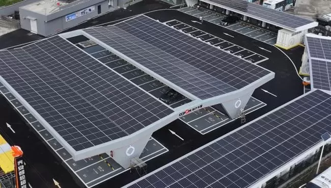
Understanding the Operational Mechanics of a BESS System for Solar
A bess system for solar acts as an electrochemical buffer. During periods of surplus photovoltaic generation, the system captures excess direct current (DC) electricity, preventing plant curtailment. Rather than curtailing generation when grid demand is low, energy is transferred into stationary battery arrays managed by advanced electronic controls.
When solar irradiance drops—due to cloud cover, late afternoon transit, or nighttime hours—the storage system instantly discharges electrical energy back into the distribution or transmission network. This conversion cycle turns variable renewable energy into a fully dispatchable asset capable of ramping up or down in milliseconds to fulfill grid commitments or internal facility loads.
Core Architecture: Four Technical Layers of Solar BESS Infrastructure
Modern utility and industrial storage systems rely on a tightly integrated hardware and software stack designed to maintain high round-trip efficiency (RTE) and long cycle life.
1. Electrochemical Battery Pack Array
The foundational layer consists of battery cells arranged in series and parallel configurations to achieve targeted system voltages (typically up to 1500V DC for utility-scale systems). While legacy installations utilized lead-acid technology, standard modern deployments utilize Lithium Iron Phosphate (LFP) chemistry due to its superior thermal stability, safety profile, high energy density, and extended cycle life (exceeding 6,000 to 8,000 cycles at 80% Depth of Discharge).
2. Power Conversion System (PCS)
The PCS serves as the bidirectional interface between the battery array and the grid infrastructure. It converts incoming AC grid or solar power into DC current during charging cycles and transforms stored DC energy back into high-quality AC power during discharge. Modern grid-scale PCS hardware incorporates grid-forming and grid-following inverter algorithms, facilitating voltage control, phase sync, and black-start capabilities.
3. Battery Management System (BMS)
Operating directly above the physical cell layer, the BMS monitors critical operational parameters: individual cell voltages, state of charge (SoC), state of health (SoH), impedance, and system temperatures. Advanced implementations by manufacturers like CNTE (Contemporary Nebula Technology Energy Co., Ltd.) integrate multi-tiered BMS control structures that isolate module faults, balance charge across rack strings, and actively prevent localized thermal runaway events.
4. Energy Management System (EMS) & Master Controller
The high-level software intelligence layer analyzes operational inputs, day-ahead power pricing, weather forecasting, and supervisory control and data acquisition (SCADA) telemetry. The EMS executes optimized charge/discharge commands automatically to capture market value through peak shaving, capacity reserve supply, or spot market arbitrage.
AC-Coupled vs. DC-Coupled Architectures: Engineering Trade-Offs
When designing a bess system for solar, system engineers must choose between two distinct coupling topologies based on site requirements, retrofit constraints, and operational goals.
DC-Coupled Architecture:
Mechanism: Photovoltaic arrays and battery storage share a common DC bus connected to a single bi-directional central inverter via DC-to-DC converters.
Efficiency: Higher round-trip efficiency (typically 92% to 95%) because power generated from the solar array charges the batteries directly without undergoing AC-to-DC conversion steps.
Ideal Application: Greenfield utility-scale installations where lower balance of system (BOS) costs and maximum conversion efficiency are primary design criteria.
AC-Coupled Architecture:
Mechanism: The PV array and the BESS run on separate inverters, interconnecting at the AC distribution transformer level.
Efficiency: Slightly lower RTE (typically 85% to 89%) due to multiple power conversion passes (DC to AC from solar panels, then AC to DC into the batteries).
Ideal Application: Brownfield retrofits for existing solar plants, or complex microgrids requiring localized system redundancy.
Commercial Financial Drivers and Grid Service Monetization
Integrating a commercial bess system for solar unlocks multiple revenue streams and operational savings models across private enterprise and public utility frameworks:
Peak Shaving and Demand-Charge Management: Industrial facilities incur substantial utility fees based on their highest 15-minute consumption window each month. Battery storage automatically discharges during high-demand periods, keeping facility utility draws below penalty thresholds.
Wholesale Energy Arbitrage: Operators store excess midday solar power when spot market prices are low or zero, releasing energy to the grid during high-demand evening pricing peaks.
Frequency Regulation & Ancillary Support: Rapid-response battery storage units absorb or inject real power within sub-second timescales to stabilize grid frequency variations (50Hz/60Hz), earning revenue through grid operator ancillary market participation.
Renewable Curtailment Prevention: Transmission line constraints often force solar assets offline during high-production hours. Onsite BESS buffers this unexportable energy, preserving long-term project revenue.
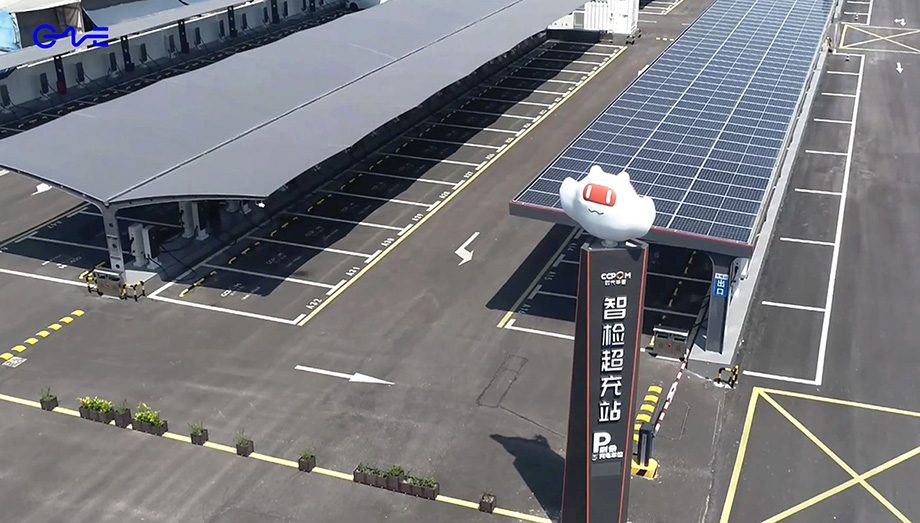
Mitigating Thermal Risk and Degradation in High-Capacity Systems
System degradation and safety management represent critical operational challenges for long-duration energy storage. Battery cells degrade due to temperature extremes, high C-rates (charge/discharge rates), and deep cycle depth.
To maximize asset lifespan beyond 15 years, industrial storage designs incorporate active thermal management. Forced liquid-cooling systems are rapidly replacing traditional ambient air conditioning. Liquid cooling plates maintain tight temperature uniformity across thousands of tightly packed cells, reducing inter-cell thermal deltas to within ±2°C. Companies such as CNTE engineer liquid-cooled energy storage containers featuring integrated multi-point gas detection, aerosol fire suppression, and redundant safety interlocks to maintain high availability while mitigating thermal runaway hazards.
Frequently Asked Questions
What is the typical lifespan of a utility-scale BESS paired with solar?
Modern LFP-based battery storage systems generally provide an operational lifespan of 10 to 15 years, or between 6,000 and 10,000 full depth-of-discharge cycles, under proper thermal management. Replacing or augmenting battery modules ("re-powering") at mid-life extends overall plant lifecycle performance up to 25 or 30 years.
How does a solar BESS respond to sudden grid outages?
When equipped with grid-forming inverters and fast-acting transfer switches, a BESS transitions from grid-following mode to islanded (microgrid) mode in milliseconds. This uninterrupted transition provides continuous power to local critical loads without operational dropouts.
What is the typical Round-Trip Efficiency (RTE) of a solar storage system?
System-level RTE accounts for energy losses in battery cell chemistry, PCS conversion, transformers, and auxiliary loads (such as thermal cooling). Modern DC-coupled LFP systems deliver system-level RTEs between 86% and 92%, whereas AC-coupled configurations operate between 83% and 88%.
Can a BESS system be added to an existing commercial solar installation?
Yes. Existing solar arrays can be retrofitted using an AC-coupled configuration. The battery system and its associated bidirectional inverter install on the facility's main AC bus bar without requiring modifications to the installed solar inverters or DC wiring array.
Why is Lithium Iron Phosphate (LFP) preferred over NMC for stationary storage?
LFP features superior chemical and thermal stability, lower susceptibility to thermal runaway, longer cycle life, and a lower bill-of-materials cost compared to Nickel Manganese Cobalt (NMC) chemistries. Because stationary systems are less constrained by volumetric energy density than electric vehicles, LFP is the preferred chemistry for stationary utility energy storage.
Partner with Industry Leaders for Modern Storage Infrastructure
Deploying energy storage requires rigorous engineering, precise integration, and battle-tested safety hardware. CNTE (Contemporary Nebula Technology Energy Co., Ltd.) specializes in enterprise-grade energy storage systems engineered to optimize power delivery, protect against grid outages, and increase economic yields for solar installations globally. Explore how advanced BESS architecture can transform your renewable power infrastructure by consulting with our technical project teams today.
Get in Touch
Recent Posts
-
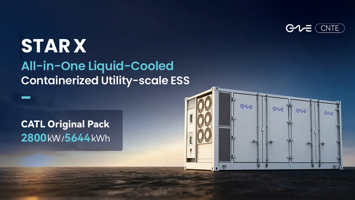
CNTE Launches STAR X Liquid-Cooled DC/AC Integrated Energy Storage System at Intersolar Europe 2026
Jul 06, 2026 -
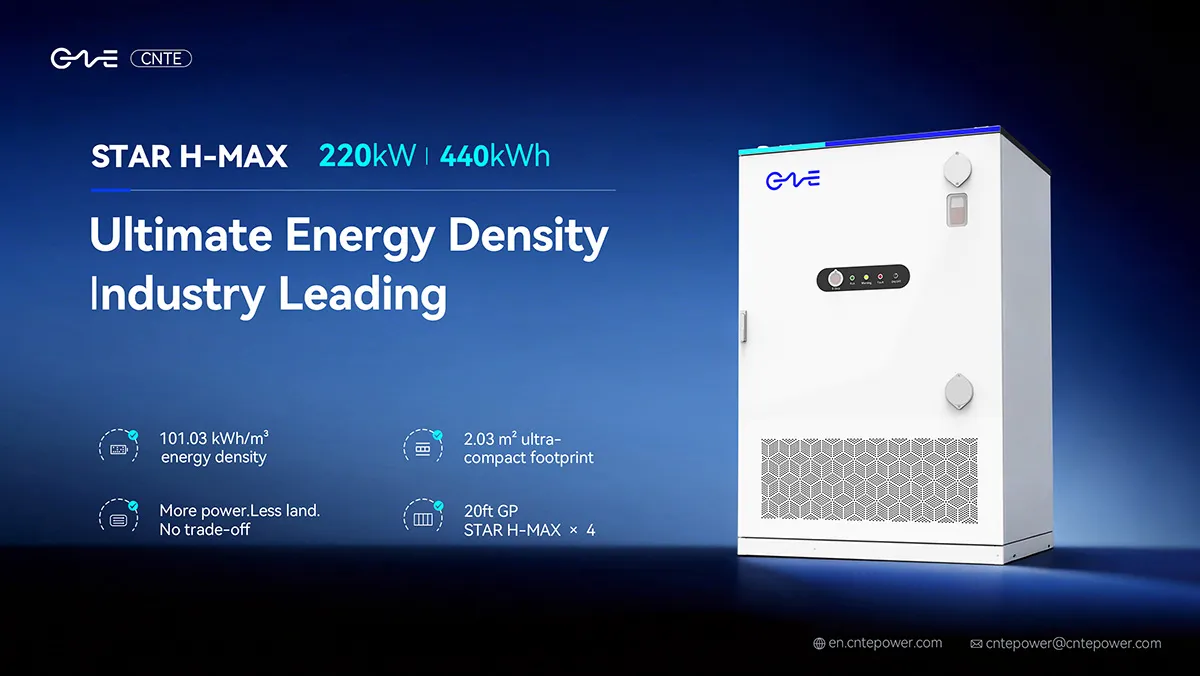
CNTE Unveils New STAR H-MAX Liquid-Cooled C&I ESS at Intersolar Europe 2026
Jun 23, 2026 -
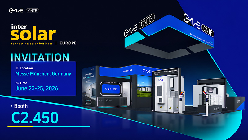
CNTE to Participate in Intersolar Europe 2026
May 20, 2026 -
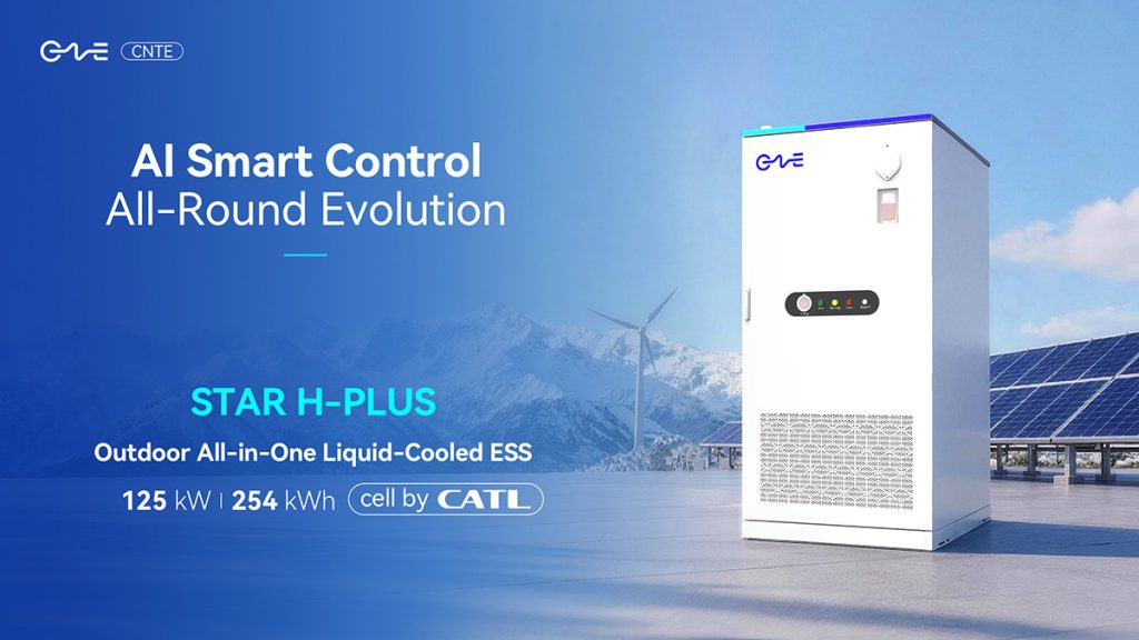
CNTE at KEY ENERGY 2026: Showcases STAR H-PLUS Outdoor Liquid-Cooled Energy Storage System
Mar 05, 2026 -

CNTE Honored as 2025 Forbes China Leading Global Brand
Jul 06, 2026 -

CNTE & YOU.ON Partner to Expand Storage Markets
May 19, 2025 -

CNTE Unveils Energy Storage Lineup at Solartech 2025
May 19, 2025 -
CNTE awarded AEO certification
Jul 06, 2026 -
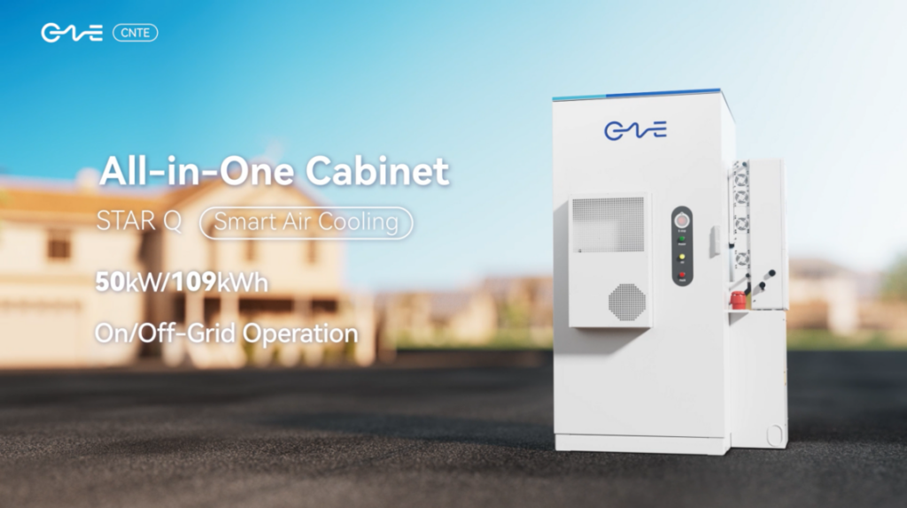
CNTE New Product Launch STAR Q
Jan 15, 2025 -

CNTE Named to Forbes China 2024 Top 30 Go-International Brands
Jul 06, 2026
