
Commercial Kilowatt Battery Systems: Technical Sizing, Architecture, and Grid Integration
The transformation of global electrical grids toward decentralized generation demands unprecedented precision in energy storage design. Industrial enterprises, distribution utilities, and commercial facilities face stringent regulatory pressures alongside escalating demand charges. Within this operational environment, the kilowatt battery serves as the primary building block for modern energy resilience, power quality management, and dynamic grid support. Moving beyond consumer-grade scale, engineering these systems requires an intimate understanding of the interplay between instantaneous power delivery, measured in kilowatts (kW), and sustained capacitive reserve, measured in kilowatt-hours (kWh).
Designing an infrastructure-grade electrochemical storage installation entails balancing cell chemistry degradation, thermal management architecture, auxiliary electrical losses, and communication topologies. Whether deployed for behind-the-meter peak mitigation or front-of-the-meter capacity reserves, selecting the appropriate system demands a technical analysis that evaluates round-trip efficiency (RTE), Levelized Cost of Storage (LCOS), and cycle life over multi-decade operational horizons.
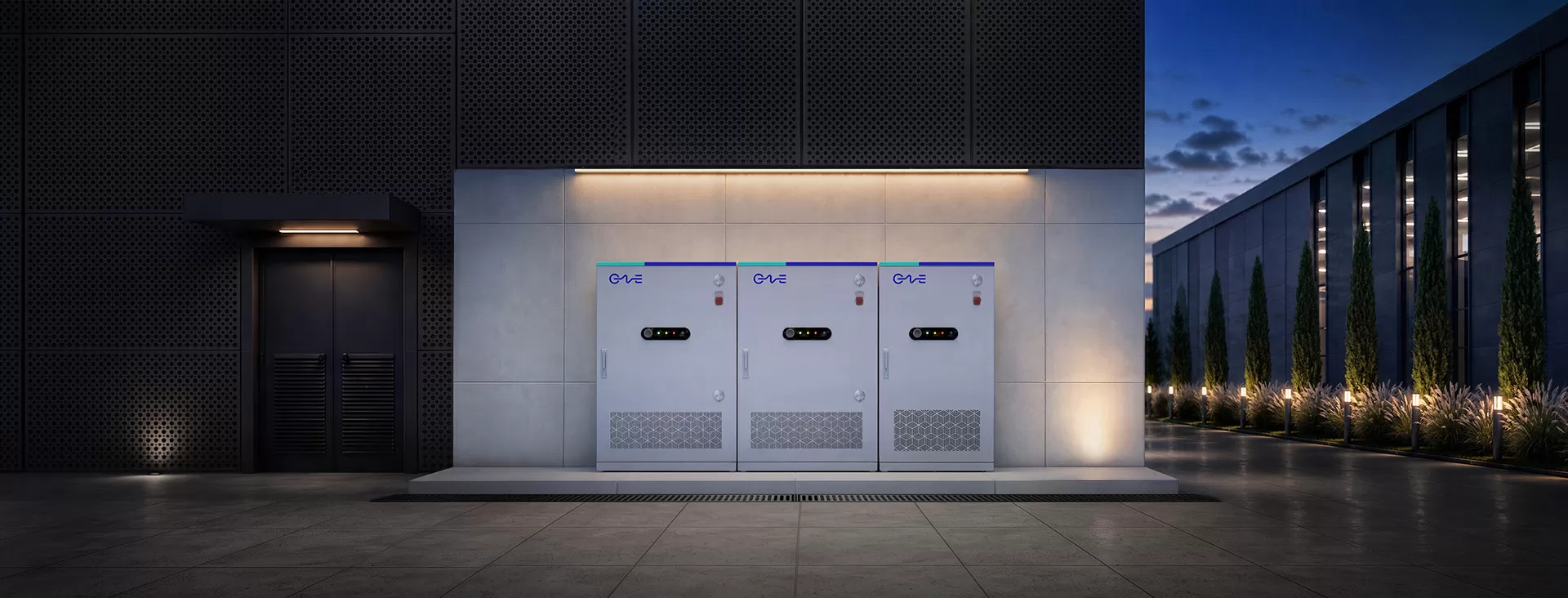
Electrochemical Characterization and C-Rate Dynamics
Industrial storage configurations rely predominantly on Lithium Iron Phosphate (LiFePO4 or LFP) cell chemistry due to its superior structural stability, predictable degradation profiles, and high cycle endurance compared to nickel-based alternatives. A robust kilowatt battery platform depends directly on matching the application's charge-discharge profile with the electrochemical limitations of the selected cell geometry, whether prismatic or high-capacity pouch.
Operating parameters dictate the thermal and electrical stress experienced by the internal components during duty cycles. Systems engineered for high-power, short-duration applications demand significantly higher C-rates, shifting the mechanical design toward minimized internal impedance and specialized busbar interconnects.
0.5C Continuous Operation: Standard for energy-shifting and four-hour demand arbitrage, balancing thermal load against cell lifespan to extend operational endurance beyond 6,000 to 8,000 cycles at 80% Depth of Discharge (DoD).
1C to 2C Peak Capabilities: Required for dynamic frequency regulation, microgrid black start sequences, and high-draw electric vehicle (EV) charging hubs, requiring localized heat-dissipating interconnects to prevent hot spots.
Internal Impedance Mitigation: Laser-welded copper-aluminum composite terminals that lower internal resistance (IR), limiting ohmic heating during heavy cycling regimens.
Thermal stability governs total system availability. While legacy systems utilized forced-air cooling, modern high-density architectures utilize closed-loop liquid thermal management. Liquid cold plates positioned adjacent to cell surfaces maintain uniform thermal distributions across dense modules, keeping intra-rack temperature deltas within a tight window of less than 3 degrees Celsius. This level of thermal parity eliminates divergent cell aging, preventing premature capacity fade across parallel strings.
System Sizing: Decoupling Power Output and Energy Capacity
A frequent error in procuring storage assets lies in conflating peak power capabilities with sustained volumetric energy. A facility requiring a 500 kW system to mitigate 15-minute operational demand spikes has vastly different technical parameters than a facility requiring 500 kW sustained over a continuous 4-hour production outage.
Specifying a commercial kilowatt battery system mandates rigorous load profile dissection, analyzing 15-minute interval data over a continuous 12-month operational window. Peak load shaving requires rapid-response inverters capable of sub-cycle switching, while prolonged duration demands oversized battery racks to compensate for end-of-life (EOL) capacity degradation, typically planned down to 70% of nominal rating.
Tier-1 system integrators like CNTE (Contemporary Nebula Technology Energy Co., Ltd.) address these complex design parameters by employing modular power conversion systems (PCS) tightly coupled to scalable DC battery blocks. Decoupling the DC battery chemistry from the AC inverter stage grants operators the flexibility to augment capacity as their baseline operational profile shifts, ensuring the initial capital expenditure aligns with immediate load profiles while preserving future scalability.
Power Conversion Systems and Grid-Interconnection Topologies
The interface between the DC battery blocks and the alternating current distribution network dictates overall round-trip efficiency. High-voltage DC topologies operating between 1000V and 1500V have superseded historical 400V DC architectures, dramatically reducing resistive copper losses across internal distribution cabling and optimizing PCS conversion efficiency.
Grid-Following vs. Grid-Forming Capabilities
Grid-following inverters rely on the presence of an existing, stable grid voltage and frequency reference, tracking the waveform via phase-locked loops (PLL). While cost-effective for standard grid-tied peak shaving, grid-following systems cannot supply stable power during full grid blackouts. Grid-forming inverters generate their own voltage and frequency references, operating as true synthetic inertia sources capable of islanding facilities instantly during utility loss and stabilizing local microgrids.
Power Quality and Four-Quadrant Inverter Control
Modern industrial energy storage systems provide ancillary grid support beyond real power discharge. Four-quadrant PCS platforms dynamically inject or absorb reactive power (VAR), mitigating facility power factor penalties without requiring discrete capacitor banks. Active filtering attenuates total harmonic distortion (THD) generated by non-linear industrial loads, including variable frequency drives (VFDs) and heavy machinery, stabilizing the internal voltage profile across the plant floor.
Integration Architectures: Battery Management and System Supervisory Control
Operational safety, longevity, and regulatory compliance rely on layered control systems operating seamlessly across hardware boundaries. The control architecture functions across three discrete hierarchical tiers:
Tier 1: Module-Level Slave BMS: Directly monitors individual cell voltages down to millivolt accuracy, parallel surface temperatures, and balancing shunts to regulate state-of-charge (SoC) balance dynamically across the series string.
Tier 2: Rack-Level Master BMS: Aggregates string telemetry, manages string contactors, coordinates DC-side ground fault detection, and executes high-speed isolation in the event of current or voltage boundary excursions.
Tier 3: Facility Energy Management System (EMS): Interfaces with the building automation system (BAS) or utility supervisory control and data acquisition (SCADA) network using protocols like Modbus TCP/IP, DNP3, or IEC 61850. The EMS processes predictive algorithms to deploy battery capacity according to day-ahead utility pricing, weather forecasts, and historical facility load curves.
Advanced implementations engineered by CNTE utilize edge-computing industrial controllers within their EMS platforms to execute local AI-driven dispatch schedules. This rapid computational execution minimizes reaction latency, capturing sub-second utility billing spikes and automatically participating in localized frequency response programs.
Commercial, Industrial, and Multi-Scenario Applications
Deploying a commercial-grade kilowatt battery provides multi-tiered value propositions spanning various industrial operations. Behind-the-meter (BTM) systems directly reduce monthly operational expenditures by flattening volatile demand peaks. Facilities subjected to high-tariff time-of-use (TOU) billing charge storage blocks during low-cost overnight periods and discharge during peak midday rate regimes, shifting loads without disrupting daily production.
For operations integrating on-site renewable generation, intermittent solar PV outputs lead to severe grid injection limits and reverse power flow restrictions. Co-locating DC-coupled or AC-coupled energy storage captures clipped solar generation, smoothing output variations and transforming variable generation into dispatchable base-load power.
Critical manufacturing processes, automated logistics warehouses, and pharmaceutical laboratories face catastrophic financial losses during momentary voltage sags or sustained brownouts. Installing an integrated energy storage system equipped with static transfer switches (STS) enables uninterrupted power supply (UPS) capabilities at the facility scale, seamlessly bridging the temporal gap between grid disconnection and secondary generator synchronization.
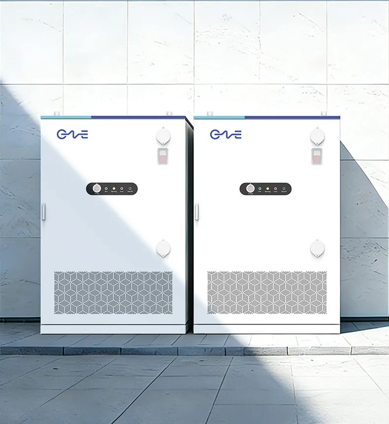
LCOS, Operational Degradation, and Lifecycle Optimization
Evaluating an energy storage investment strictly on upfront capital cost per kilowatt-hour yields an incomplete operational picture. Levelized Cost of Storage (LCOS) accounts for total lifecycle expenses, calculating capital expenditure, scheduled maintenance, auxiliary power consumption, round-trip efficiency losses, and end-of-life battery module augmentation.
Electrochemical cells naturally degrade through two parallel vectors: calendar aging and cycling aging. Calendar degradation occurs continuously regardless of usage, dictated primarily by ambient storage temperature and sustained average state-of-charge. Cycling degradation stems from mechanical stresses inside the cathode and anode materials during lithium-ion intercalation and de-intercalation, alongside solid electrolyte interphase (SEI) layer growth over time.
Restricting DoD Windows: Limiting cycle parameters to between 10% and 90% SoC dramatically suppresses mechanical strain, often extending usable cycle life by more than 35% compared to operating continuously between 0% and 100% SoC.
Auxiliary Parasitic Loads: High-efficiency liquid cooling loops with variable-speed variable-flow pumps reduce the continuous parasitic electrical draw, maintaining a higher net AC-to-AC round-trip efficiency over decades of operation.
Planned Augmentation Schedules: Designing system racks with spare DC bus integration capacity allows operators to install supplemental battery modules at year 7 or 10, compensating for natural capacity fade without requiring full system replacement.
Frequently Asked Questions
What is the functional difference between a kilowatt and a kilowatt-hour in battery specifications?
A kilowatt (kW) denotes the instantaneous power capacity of the battery system, representing the maximum rate at which electrical energy can be discharged or absorbed at any given moment. A kilowatt-hour (kWh) quantifies the total volumetric electrical energy stored within the electrochemical cells over time. A 250 kW / 500 kWh system delivers a maximum continuous power output of 250 kW for two hours before reaching its maximum depth of discharge.
How does the thermal management system affect the operational life of an industrial kilowatt battery?
Battery cell internal resistance rises exponentially at lower operating temperatures, whereas elevated temperatures accelerate chemical side reactions, cathode dissolution, and SEI layer growth. Closed-loop liquid cooling maintains optimal cell operating conditions between 20°C and 25°C with minimal thermal variance across the enclosure. Mitigating temperature differentials prevents uneven string aging, eliminates localized hot spots, and preserves factory-rated cycle life across the entire asset.
Can a grid-tied commercial battery system provide seamless backup during a utility power failure?
Standard grid-tied inverters automatically disconnect during utility outages to comply with anti-islanding safety regulations, shutting down the storage asset entirely. Seamless backup power requires an integrated system equipped with an external static transfer switch (STS) and grid-forming inverters capable of four-quadrant black-start operation. When a utility fault occurs, the STS physically isolates the facility from the external grid within milliseconds, while the inverter establishes an internal microgrid frequency and voltage reference to maintain uninterrupted operations.
What routine maintenance is required for a commercial-scale energy storage system?
While stationary electrochemical systems eliminate the intensive mechanical maintenance associated with diesel generators, scheduled preventative maintenance remains mandatory. Semi-annual protocols include inspecting high-voltage DC torque connections with calibrated thermal cameras, testing liquid coolant chemistry and pressure levels, checking auxiliary UPS power systems, verifying emergency venting actuators, and cleaning dust accumulation from heat exchangers and inverter intake filters. Periodic firmware updates and BMS sensor recalibrations are also necessary to maintain state-of-charge tracking precision.
How is end-of-life defined for an industrial-grade battery installation?
End-of-life (EOL) for a commercial storage installation is conventionally defined as the operational point where the battery system's retainable capacity degrades to 70% or 80% of its initial rated capacity. While the system remains electrically operational beyond this threshold, the diminished energy reserve can no longer support full intended peak-shaving profiles or baseline emergency runtimes. Upon reaching EOL, operators execute module augmentation plans or decommission the cells for secondary life applications or raw material recycling.
Engineering Consultation and Project Specifications
Specifying an industrial energy storage asset requires deep alignment between facility electrical engineering teams, system integrators, and equipment manufacturers. Calculating exact peak-shaving parameters, optimizing round-trip efficiency, and designing scalable high-voltage architectures requires comprehensive analysis of facility load profiles and regional interconnect standards.
CNTE provides dedicated application engineering services to evaluate existing distribution infrastructure, model multi-year LCOS curves, and deliver fully integrated containerized storage platforms tailored to complex industrial environments. Contact the technical engineering division today to submit your single-line diagrams, historical 15-minute interval demand data, and facility expansion plans for a comprehensive engineering evaluation and detailed commercial proposal.
Get in Touch
Recent Posts
-
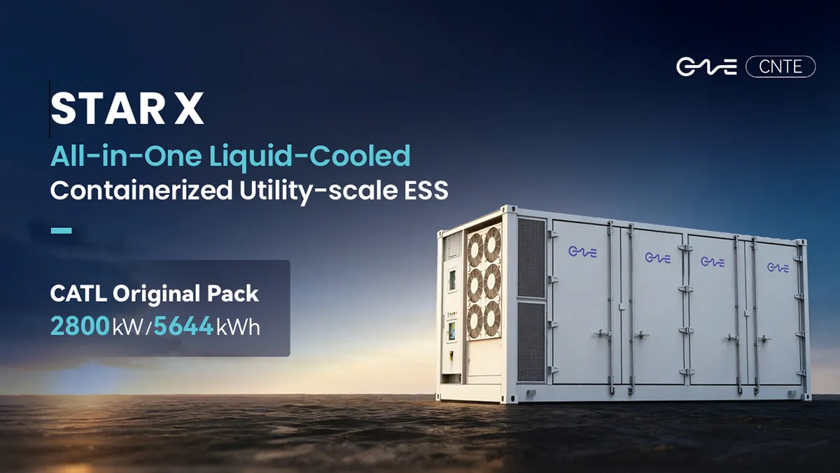
CNTE Launches STAR X Liquid-Cooled DC/AC Integrated Energy Storage System at Intersolar Europe 2026
Jul 06, 2026 -
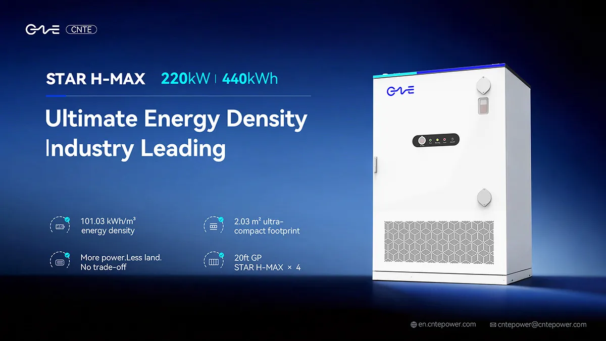
CNTE Unveils New STAR H-MAX Liquid-Cooled C&I ESS at Intersolar Europe 2026
Jun 23, 2026 -
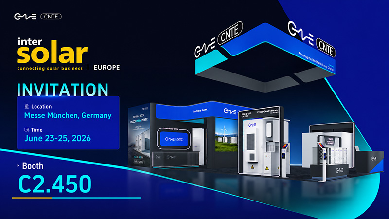
CNTE to Participate in Intersolar Europe 2026
May 20, 2026 -
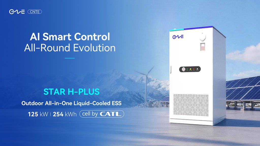
CNTE at KEY ENERGY 2026: Showcases STAR H-PLUS Outdoor Liquid-Cooled Energy Storage System
Mar 05, 2026 -

CNTE Honored as 2025 Forbes China Leading Global Brand
Jul 06, 2026 -

CNTE & YOU.ON Partner to Expand Storage Markets
May 19, 2025 -

CNTE Unveils Energy Storage Lineup at Solartech 2025
May 19, 2025 -
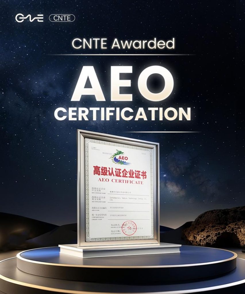
CNTE awarded AEO certification
Jul 06, 2026 -
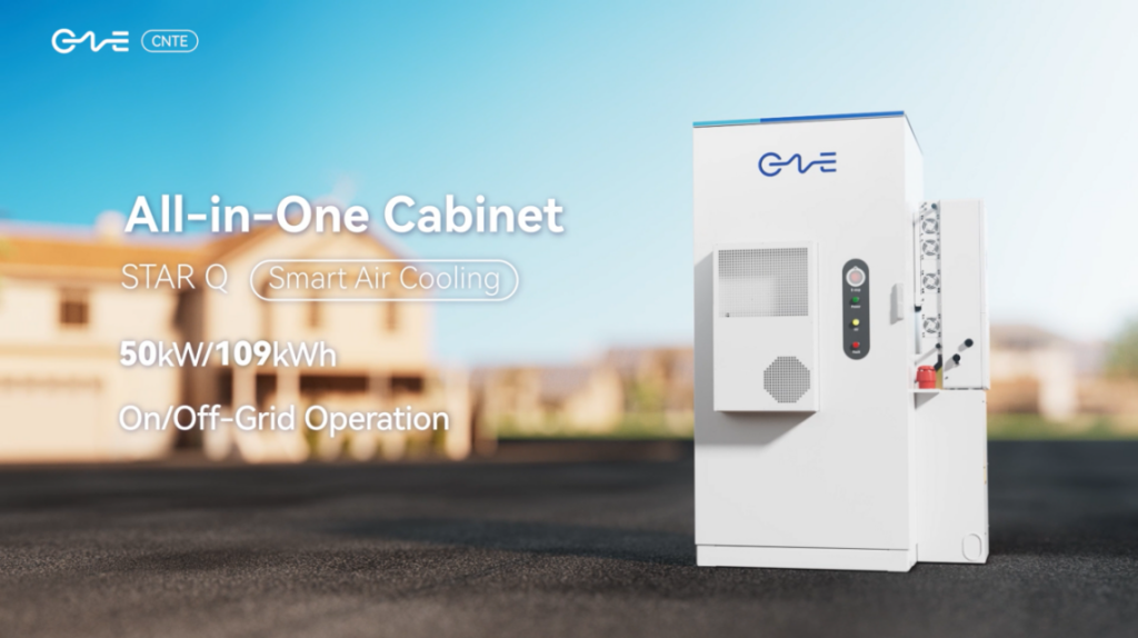
CNTE New Product Launch STAR Q
Jan 15, 2025 -

CNTE Named to Forbes China 2024 Top 30 Go-International Brands
Jul 06, 2026
