What Operational Parameters Define the Largest Energy Storage System in the World?
High-voltage electrical transmission networks face unprecedented grid imbalances due to the rapid integration of variable renewable energy sources. Solar photovoltaic installations and wind generation assets produce highly fluctuating electrical outputs that rarely align with consumer load demand curves. To balance these high-voltage transmission networks, developers and utility operators are deploying ultra-large-scale battery installations. Achieving grid stabilization at this scale requires a comprehensive understanding of the physical, thermal, and electrical parameters behind the largest energy storage system in the world. As these utility-scale projects scale from megawatt-hour to gigawatt-hour levels, the demands placed on thermal management, battery management systems, and power conversion systems become increasingly complex.
CNTE (Contemporary Nebula Technology Energy Co., Ltd.) focuses on developing highly stable energy storage solutions that address these large-scale grid requirements. By focusing on advanced liquid-cooling mechanisms and integrated battery management topologies, modern systems can operate with higher efficiency, extended cycle life, and lower operational overheads, even when scaled to serve regional power grids.

Defining the Scale of Utility-Grade Battery Storage
Understanding what constitutes the largest energy storage system in the world requires analyzing both continuous power capacity (measured in megawatts, MW) and total energy storage capacity (measured in megawatt-hours, MWh). Power capacity dictates the maximum rate at which the system can inject or absorb electricity from the grid, while energy capacity defines the duration for which this power can be sustained. For utility-scale installations, a system may be rated at 500 MW / 2000 MWh, indicating a four-hour discharge capability.
To achieve these capacities, thousands of individual lithium iron phosphate (LFP) cells are wired in complex series and parallel configurations. Managing these massive arrays demands a modular architecture where cells are grouped into modules, modules into racks, and racks into high-voltage direct current (DC) blocks. A typical utility-scale DC block operates at voltages up to 1500V DC, a level chosen to minimize transmission losses and reduce the required gauge of copper cabling across the project site.
Thermal Management Systems: Liquid vs. Forced Air
Operating a utility-scale battery installation generates substantial heat, primarily due to internal resistance within the cells during high-current charging and discharging cycles. If this thermal energy is not dissipated uniformly, localized hot spots develop, accelerating cell degradation and introducing thermal runaway hazards. Maintaining a uniform temperature across every cell in the facility is a primary objective for utility operators.
Historically, forced-air cooling was the standard method for heat dissipation. However, air has a low specific heat capacity (approximately 1.005 kJ/kg·K), making it highly inefficient for dense battery configurations. Liquid cooling, using a mixture of water and ethylene glycol, has become the preferred standard for the largest energy storage system in the world. Liquid-cooled systems utilize cooling plates directly integrated with the battery modules, achieving a heat transfer coefficient significantly higher than air-based systems.
Temperature Uniformity: Advanced liquid cooling systems maintain a temperature variance of less than 3 degrees Celsius across the entire battery rack, ensuring uniform aging of the cells.
Parasitic Load Reduction: Liquid cooling pumps require less electrical power to move fluid than massive fan arrays require to force air through dense enclosures, reducing internal power consumption.
Enclosure Density: Liquid-cooling loops allow for tighter cell packaging, decreasing the overall footprint of the utility installation by up to 40% compared to traditional air-cooled setups.
By implementing closed-loop liquid cooling configurations, CNTE provides utility operators with systems capable of sustaining continuous C-rates without triggering thermal throttling. This thermal stability translates directly into longer operational lifespans and more predictable discharge performance over decades of service.
Grid Integration and Power Quality Control
Integrating a gigawatt-scale battery system into an existing high-voltage transmission network requires sophisticated power electronics. The conversion of direct current stored in the batteries to alternating current (AC) utilized by the utility grid is managed by bi-directional Power Conversion Systems (PCS). These inverters must not only convert electricity efficiently but also provide ancillary services to the grid operator.
One primary service is frequency regulation. If grid frequency drops below nominal levels (typically 50Hz or 60Hz depending on the region), the battery system must inject power within milliseconds to arrest the decline. Conversely, if excess generation causes the frequency to rise, the system must rapidly absorb power. This fast frequency response (FFR) requires high-speed digital signal processors and low-latency communication networks between the substation controllers and the individual inverter units.
Voltage support is another vital function. Large battery installations can inject or absorb reactive power (VARs) to stabilize local grid voltage levels, preventing brownouts or overvoltage conditions in areas with high renewable penetration. This process must occur automatically without compromising the primary active power dispatch targets of the facility.
Advanced Battery Management Architecture
At the core of the largest energy storage system in the world is a multi-tiered Battery Management System (BMS). The BMS acts as the brain of the installation, monitoring voltage, current, temperature, and State of Charge (SoC) at multiple levels of the system hierarchy.
The first tier consists of local monitoring units directly attached to individual cell groups. These units measure cell voltage with millivolt-level accuracy and monitor surface temperatures to detect localized heating anomalies. The second tier, or cluster BMS, aggregates data from multiple modules within a single high-voltage rack, managing balancing currents to keep all cells at an equal state of charge.
The third tier is the system-level BMS, which interfaces with the overall plant supervisory control and data acquisition (SCADA) network. This high-level system calculates real-time State of Health (SoH) metrics, estimates remaining life, and communicates operational limits to the power conversion system to prevent overcharging or overdischarging. CNTE designs integrated BMS solutions that employ high-frequency data sampling and predictive modeling to identify micro-short circuits or cell inconsistencies before they lead to systemic failure.
Degradation Mitigation and Financial Lifespan
The capital expenditure required to construct massive battery installations demands a long operational lifespan, typically targeting 15 to 20 years of continuous service. The primary threat to this lifespan is cell capacity fade, which occurs due to both cycling aging (caused by charge and discharge cycles) and calendar aging (caused by time and temperature exposure).
To slow down these degradation mechanisms, system operators use specific charging profiles and state-of-charge limits. For instance, operating a system between 10% and 90% SoC rather than utilization of the full 0% to 100% span can double the cycle life of LFP chemistry. Minimizing the time cells spend at high states of charge and elevated temperatures prevents the growth of the solid electrolyte interphase (SEI) layer inside the cell, which consumes active lithium ions over time.
Furthermore, structural developments in cell-to-pack (CTP) integration remove unnecessary structural elements within the battery rack, replacing them with high-efficiency thermal barriers. These barriers prevent thermal propagation from a single compromised cell to adjacent cells, isolating localized incidents and preserving the operational integrity of the wider plant.
Industrial and Behind-the-Meter Application Scenarios
While utility-scale projects dominate discussions regarding total capacity, large-scale storage systems are increasingly deployed behind-the-meter (BTM) at heavy industrial sites, mining operations, and large manufacturing hubs. These industrial systems address localized grid constraints, mitigate high demand charges, and secure continuous power for sensitive manufacturing processes.
For industrial facilities with heavy motor-starting loads or arc furnaces, localized storage systems provide immediate power injection to prevent voltage sags that can disrupt automated assembly lines. By storing energy during off-peak hours when electricity prices are low and discharging it during peak demand periods, industrial enterprises can significantly reduce their operational energy costs. CNTE supplies tailored behind-the-meter installations that seamlessly coordinate with onsite solar arrays and industrial microgrids, ensuring uninterrupted power availability in regions with weak grid infrastructure.

Inquiry and Consultative Engineering Services
Designing, scaling, and deploying utility-grade energy storage systems involves complex electrical engineering, thermodynamic analysis, and local grid compliance procedures. Each project requires a custom evaluation of grid connection points, environmental conditions, and specific operational duties.
CNTE provides complete, end-to-end engineering support for developers, utilities, and industrial enterprises planning high-capacity storage installations. Our team of specialists assists with capacity planning, thermal simulation, power quality analysis, and system integration strategies. Contact our engineering office to discuss your project requirements and receive detailed technical specifications for your next energy storage development.
Frequently Asked Questions
Q1: What are the main differences between LFP and NMC chemistries in utility-scale installations?
A1: Lithium Iron Phosphate (LFP) is the preferred chemistry for utility-scale energy storage due to its long cycle life (often exceeding 6,000 to 8,000 cycles), high thermal stability, and lower raw material costs. Nickel Manganese Cobalt (NMC) chemistry offers higher energy density, making it suitable for electric vehicles, but its shorter cycle life and lower thermal stability make it less suitable for long-duration grid installations where space constraints are less critical.
Q2: How does liquid cooling improve the lifespan of the largest energy storage system in the world?
A2: Liquid cooling provides direct thermal contact with battery cells or modules, achieving a higher heat transfer coefficient than air cooling. This ensures that the temperature difference between the hottest and coldest cells remains within a very narrow window (typically under 3°C). Minimizing thermal gradients prevents uneven aging across the battery pack, preserving overall capacity and extending the operational lifespan of the entire system.
Q3: What is the role of a Power Conversion System (PCS) in high-voltage battery storage?
A3: The PCS acts as a bi-directional inverter that bridges the DC battery system with the AC utility grid. During charging, it converts high-voltage AC grid power into high-voltage DC power to charge the battery cells. During discharge, it converts the stored DC power back into synchronized AC power. The PCS also manages power factor correction, voltage regulation, and fast frequency response duties.
Q4: Why is a three-tiered BMS architecture necessary for utility-scale battery systems?
A4: Large installations consist of hundreds of thousands of individual cells. A three-tiered Battery Management System (BMS) manages this scale by delegating tasks: the cell-level BMS monitors individual cell voltage and temperature; the cluster-level BMS balances voltages within a single rack; and the system-level BMS coordinates overall operation, calculates health metrics, and interfaces with the external utility dispatch system.
Q5: How do grid-scale battery systems help integrate intermittent renewable energy?
A5: Grid-scale systems absorb excess electricity generated by solar and wind plants during periods of high generation and low demand. This stored energy is then discharged back into the grid during peak demand hours or when environmental conditions reduce renewable generation. This mechanism, known as energy arbitrage or load shifting, prevents renewable curtailment and stabilizes grid frequency.
Get in Touch
Recent Posts
-
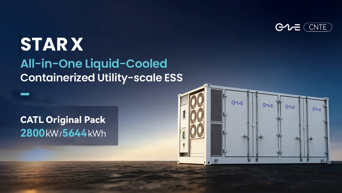
CNTE Launches STAR X Liquid-Cooled DC/AC Integrated Energy Storage System at Intersolar Europe 2026
Jul 06, 2026 -
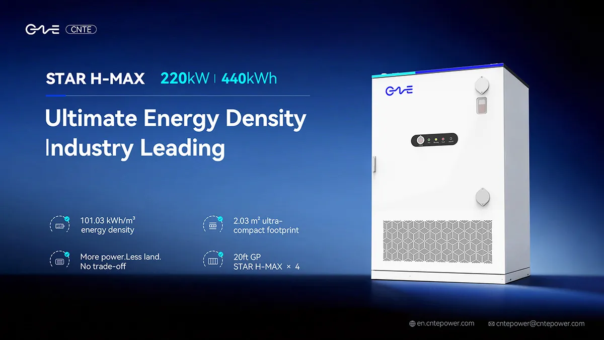
CNTE Unveils New STAR H-MAX Liquid-Cooled C&I ESS at Intersolar Europe 2026
Jun 23, 2026 -
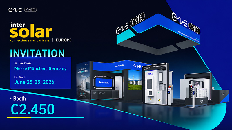
CNTE to Participate in Intersolar Europe 2026
May 20, 2026 -
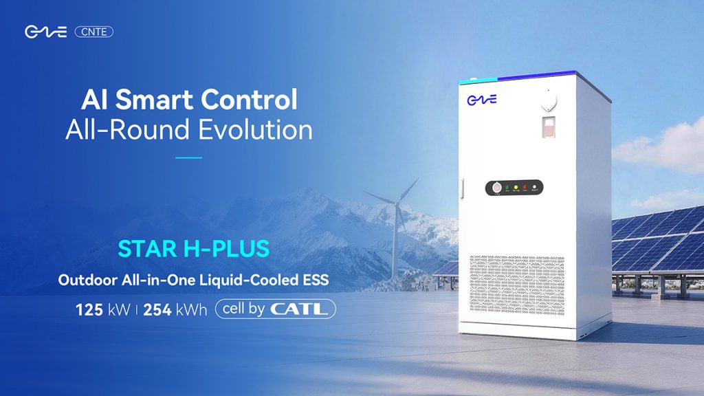
CNTE at KEY ENERGY 2026: Showcases STAR H-PLUS Outdoor Liquid-Cooled Energy Storage System
Mar 05, 2026 -

CNTE Honored as 2025 Forbes China Leading Global Brand
Jul 06, 2026 -
CNTE & YOU.ON Partner to Expand Storage Markets
May 19, 2025 -
CNTE Unveils Energy Storage Lineup at Solartech 2025
May 19, 2025 -
CNTE awarded AEO certification
Jul 06, 2026 -
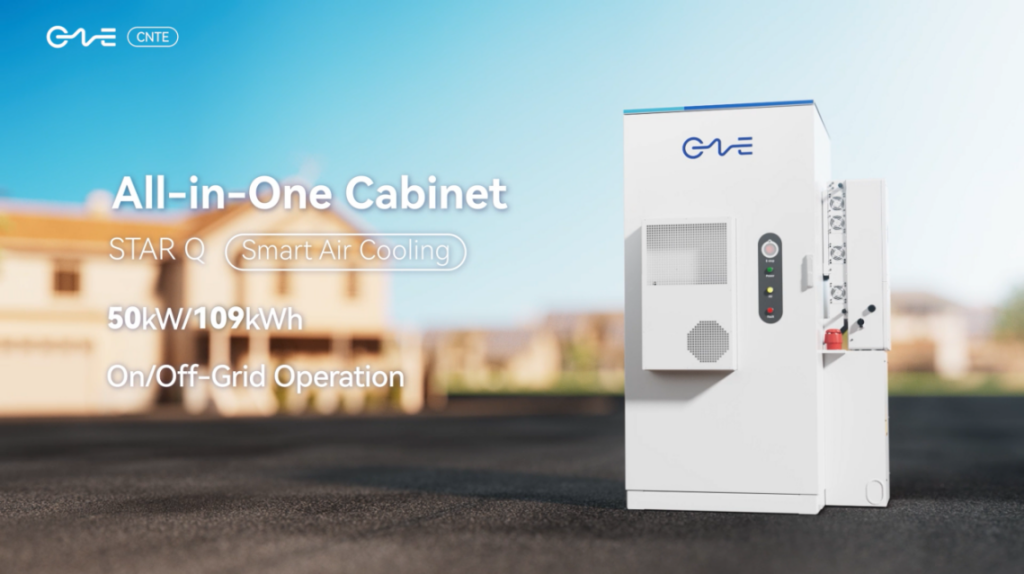
CNTE New Product Launch STAR Q
Jan 15, 2025 -
CNTE Named to Forbes China 2024 Top 30 Go-International Brands
Jul 06, 2026