On Grid Solar Battery Storage: Enhancing Grid Stability and Commercial ROI
The transition toward distributed energy resources requires advanced infrastructure to balance supply and demand variations. High-penetration photovoltaic generation introduces operational challenges for local utility distribution systems, including voltage fluctuations and reverse power flows. Implementing an on grid solar battery storage system offers commercial and industrial facilities a viable method to stabilize power quality, manage operational expenditures, and secure auxiliary revenues. By storing excess generation and discharging it strategically, these systems bridge the gap between volatile renewable production and rigid electrical consumption profiles.
CNTE (Contemporary Nebula Technology Energy Co., Ltd.) designs utility-grade and commercial battery integration platforms that facilitate grid synchronization. Understanding the underlying electrical architecture, system sizing parameters, and thermal management mechanisms is necessary for engineers and facility managers seeking to implement these solutions.

Architectural Foundations of Grid-Tied Energy Storage
An on grid solar battery storage configuration depends on the integration of power electronics, electrochemical cells, and digital control layers. Unlike off-grid setups that operate in isolation, grid-interactive systems must continuously synchronize with the utility grid frequency and voltage levels.
Power Conversion Systems
The Power Conversion System (PCS) serves as the bi-directional interface between the direct current (DC) battery bank and the alternating current (AC) grid network. Modern PCS units utilize high-frequency insulated-gate bipolar transistors (IGBTs) or silicon carbide (SiC) semiconductors to convert power with high efficiency. These inverters operate in grid-following mode under normal conditions, locking onto the utility voltage vector using phase-locked loop (PLL) algorithms. In advanced microgrid setups, they can transition to grid-forming mode to provide local voltage reference during outages.
Battery Management Systems
The Battery Management System (BMS) operates as a multi-tier control architecture. The lowest level monitors individual cell parameters, such as voltage, temperature, and internal resistance. The intermediate level consolidates this data to calculate the overall State of Charge (SoC) and State of Health (SoH). The master BMS communicates directly with the high-level system controllers, coordinating safety functions, circuit breaker operations, and cell balancing to prevent accelerated cell degradation.
Energy Management Systems
The Energy Management System (EMS) acts as the operational brain of the setup. It collects data from meteorological sensors, utility pricing feeds, local load meters, and the BMS. Through predictive algorithms, the EMS decides when to charge the battery from the PV array, when to hold the energy, and when to discharge it into the facility network or back to the utility grid. This real-time decision-making process ensures the facility aligns with local tariff structures and grid constraints.
| Component | Primary Function | Key Performance Indicators |
|---|---|---|
| Electrochemical Cells | Energy storage via Lithium Iron Phosphate chemistry | Energy density, cycle life, thermal runaway threshold |
| Power Conversion System (PCS) | Bi-directional AC/DC power conversion | Conversion efficiency, response time, harmonic distortion |
| Battery Management System (BMS) | Cell-level monitoring, balancing, and safety execution | Voltage measurement accuracy, balancing current capacity |
| Energy Management System (EMS) | System orchestration, dispatch scheduling, and communication | Data sampling rate, algorithm processing speed, protocol compatibility |
Primary Use Cases in Commercial and Industrial Sectors
Commercial and industrial (C&I) enterprises face complex energy billing mechanisms, which often include high demand charges based on the peak 15-minute consumption interval of the month. Utilizing on grid solar battery storage allows businesses to reshape their demand profiles and secure financial benefits.
Peak Shaving and Demand Charge Reduction
Demand charges can represent up to 50 percent of a commercial electricity bill. When facility operations demand sudden spikes in power—such as starting heavy machinery or industrial cooling units—the EMS triggers the battery system to discharge. This immediate injection of power caps the demand drawn from the utility grid, maintaining the peak consumption below a predetermined threshold and directly reducing monthly capacity tariffs.
Load Shifting and Time-of-Use Rate Arbitrage
Utilities frequently implement Time-of-Use (ToU) tariffs, where electricity prices peak during late afternoon and early evening hours. An on grid solar battery storage system enables facilities to store solar power generated during off-peak morning hours. Instead of exporting this energy to the grid at low feed-in tariffs, the facility consumes the stored power during peak price periods, avoiding expensive retail utility rates.
Photovoltaic Self-Consumption Maximization
In regions where feed-in tariffs have expired or are non-existent, exporting excess PV energy to the grid yields zero financial return. Capturing surplus solar generation on-site and storing it for later use ensures that every kilowatt-hour generated by the PV array is used internally, lowering the reliance on external energy purchases and enhancing overall facility self-sufficiency.
Ancillary Grid Services
Large-scale energy storage assets can participate in utility demand response programs and ancillary service markets. These services include fast frequency response, voltage support, and operating reserves. By responding to utility dispatch signals within milliseconds, commercial storage installations can generate secondary revenue streams through capacity payments and frequency stabilization credits.
System Chemistry and Thermal Management
The physical composition and thermodynamic control of the battery cells determine the operational lifetime and return on investment for any storage project.
Lithium Iron Phosphate (LFP) Dominance
LFP chemistry has become the industry standard for stationary energy storage systems, surpassing Nickel Manganese Cobalt (NMC) variants. This preference stems from the structural stability of the olivine crystal arrangement in LFP, which exhibits superior thermal stability and resists oxygen release at high operating temperatures. LFP cells offer extensive cycle life, often exceeding 6,000 cycles at an 80 percent Depth of Discharge (DoD), making them highly suitable for daily cyclic operations in grid-interactive installations.
Liquid Cooling versus Forced Air Systems
Maintaining uniform cell temperatures is vital to prevent localized aging and cell mismatch within large battery enclosures. Traditional forced-air cooling systems struggle to maintain uniform temperatures across dense battery racks, often resulting in temperature differentials of 5°C to 10°C. Liquid cooling systems, utilized in high-density CNTE storage enclosures, circulate dielectric fluid or glycol mixtures through cooling plates adjacent to the cells. This method limits cell-to-cell temperature variations to less than 3°C, which helps preserve capacity and improves the system's Round-Trip Efficiency (RTE).
Engineering Integration and Standard Compliance
Implementing an industrial storage installation requires attention to electrical engineering protocols, grid connection codes, and safety standards.
Grid Code Compliance and Interconnection Standards
Grid-tied energy assets must comply with national and regional interconnection standards, such as IEEE 1547 in North America or EN 50549 in Europe. These standards dictate how the system must behave during grid anomalies, including low-voltage ride-through (LVRT) and over-frequency power droop responses. The PCS must be certified to detect grid disconnects promptly to prevent islanding—a dangerous condition where the system continues to energize a local utility line during a utility outage.
Safety Standards and System Certification
To secure permits and insurance, storage systems must meet rigorous safety protocols. Key standards include:
UL 1973: Standard for batteries for use in stationary, vehicle auxiliary power, and light electric rail applications, focusing on cell safety under electrical, mechanical, and environmental stress.
UL 9540: Standard for safety of energy storage systems and equipment, covering the complete system integration of the electrochemical storage unit, PCS, and thermal control.
UL 9540A: Test method for evaluating thermal runaway fire propagation in battery systems, providing quantitative data on potential gas emissions and thermal behavior.
IEC 62619: International safety requirements for secondary lithium cells and batteries used in industrial applications.

The Role of CNTE in Industrial Decarbonization
CNTE (Contemporary Nebula Technology Energy Co., Ltd.) addresses the evolving demands of the global energy sector by engineering integrated on grid solar battery storage systems. These products are developed to support severe industrial load profiles while maintaining operational safety. By integrating advanced liquid cooling configurations with high-capacity LFP chemistry, CNTE systems achieve stable thermal performance and long operating lifetimes.
These systems feature high-performance power conversion electronics that integrate seamlessly with existing industrial power distribution setups. The control platforms are compatible with diverse industrial SCADA systems and standard communication protocols, including Modbus TCP and DNP3, enabling remote monitoring, diagnostics, and precise dispatch control. This ensures facility operators can maintain constant oversight over their energy assets, maximizing performance and prolonging the operational lifespan of the equipment.
Frequently Asked Questions
Q1: What is the typical round-trip efficiency of an on grid solar battery storage system?
A1: The typical AC-to-AC round-trip efficiency (RTE) of a modern commercial grid-tied storage system ranges between 85% and 90%. This metric accounts for conversion losses in the bi-directional inverter (PCS), electrochemical conversion losses within the LFP cells, and the parasitic power consumed by auxiliary systems, such as thermal management and controller units.
Q2: How does a liquid-cooled battery system compare to an air-cooled system in hot climates?
A2: Liquid cooling systems provide significantly higher thermal transfer coefficients than air-based systems. In hot climates, liquid cooling maintains internal cell temperatures within the optimal 20°C to 30°C range far more effectively, keeping temperature variations between cells under 3°C. This uniform cooling prevents localized cell degradation, limits capacity fade, and reduces parasitic fan loads compared to air cooling.
Q3: Can on grid solar battery storage systems provide backup power during a utility grid failure?
A3: Yes, provided the system is designed with grid-forming capability and an automatic transfer switch (ATS) or microgrid isolation device. When a grid outage occurs, the system must disconnect from the utility grid to prevent backfeeding, and then transition the PCS into voltage-source mode to supply backup power to the facility's critical load panel.
Q4: How long do commercial LFP batteries last in daily peak-shaving applications?
A4: High-quality Lithium Iron Phosphate (LFP) batteries subjected to one full charge-discharge cycle per day typically last between 12 and 15 years before reaching their end-of-life criteria (usually defined as retaining 70% to 80% of original capacity). Proper thermal management and maintaining the system within optimal SoC boundaries are major factors in achieving this lifespan.
Q5: What are the main requirements for connecting a large battery system to the utility grid?
A5: Grid connection requires compliance with regional interconnection standards, such as IEEE 1547. It involves securing an interconnection agreement from the local utility, installing protective relays to prevent islanding, configuring active and reactive power controls, and verifying that the system equipment carries standard safety certifications like UL 9540.
Inquire About Your Energy Storage Solution
Designing a system that balances local demand dynamics, solar production profiles, and regional utility tariffs requires detailed technical analysis. CNTE (Contemporary Nebula Technology Energy Co., Ltd.) provides comprehensive engineering services, from initial layout evaluation to system integration and commissioning.
If you are planning to deploy an on grid solar battery storage asset for your industrial facility, commercial complex, or utility-scale project, contact our application engineering team today. We will assist you in sizing the battery capacity, choosing the appropriate power conversion system, and aligning the controls with your facility's operational goals. Send an inquiry to discuss your technical specifications and request an initial system design proposal.
Get in Touch
Recent Posts
-
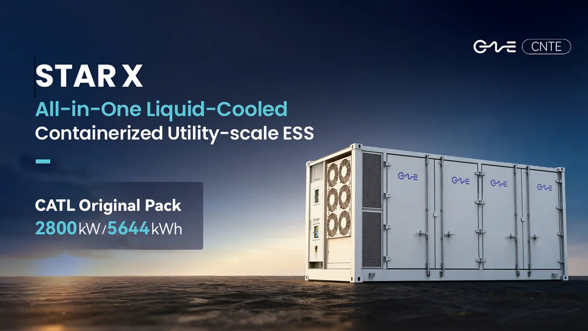
CNTE Launches STAR X Liquid-Cooled DC/AC Integrated Energy Storage System at Intersolar Europe 2026
Jul 06, 2026 -
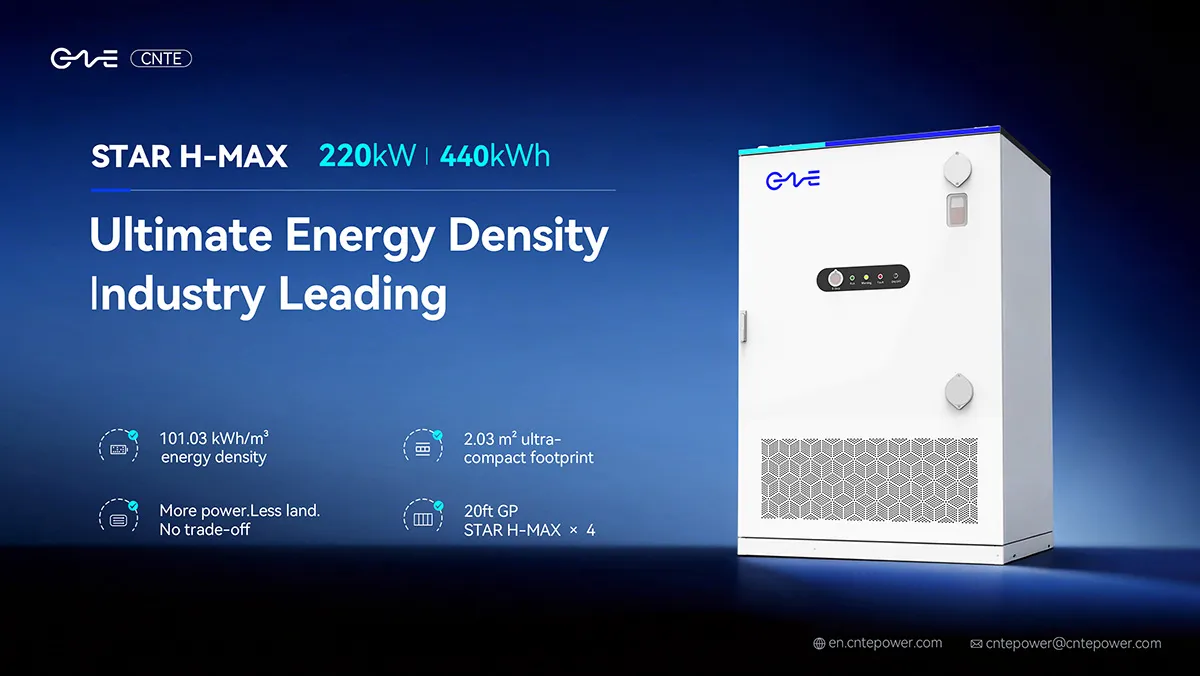
CNTE Unveils New STAR H-MAX Liquid-Cooled C&I ESS at Intersolar Europe 2026
Jun 23, 2026 -
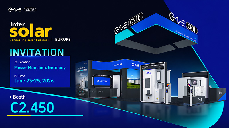
CNTE to Participate in Intersolar Europe 2026
May 20, 2026 -
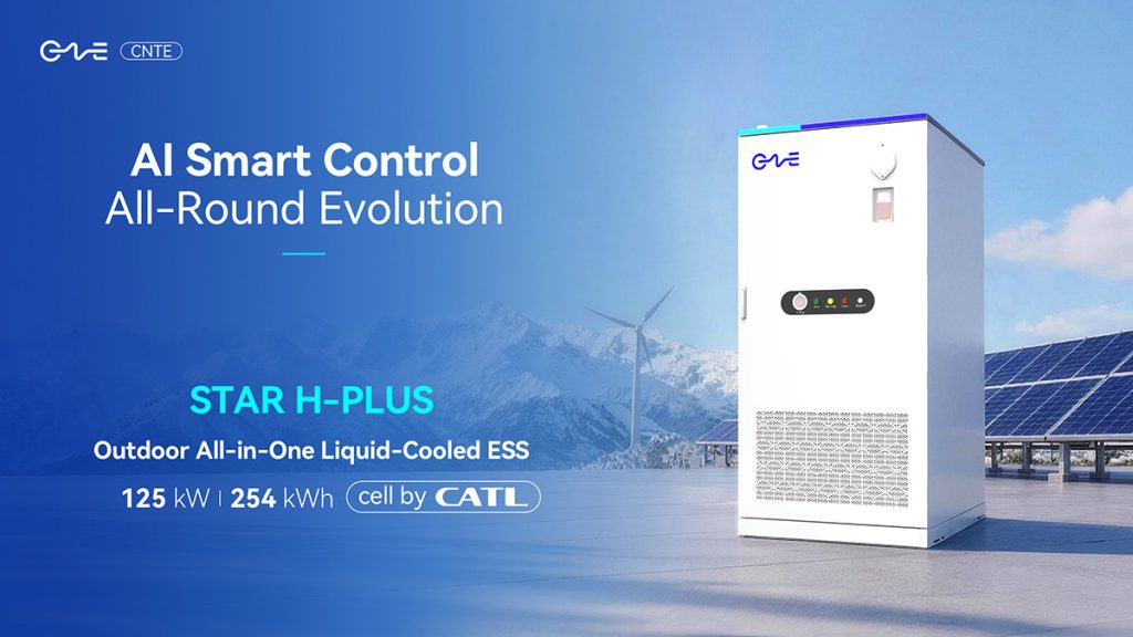
CNTE at KEY ENERGY 2026: Showcases STAR H-PLUS Outdoor Liquid-Cooled Energy Storage System
Mar 05, 2026 -

CNTE Honored as 2025 Forbes China Leading Global Brand
Jul 06, 2026 -

CNTE & YOU.ON Partner to Expand Storage Markets
May 19, 2025 -

CNTE Unveils Energy Storage Lineup at Solartech 2025
May 19, 2025 -
CNTE awarded AEO certification
Jul 06, 2026 -
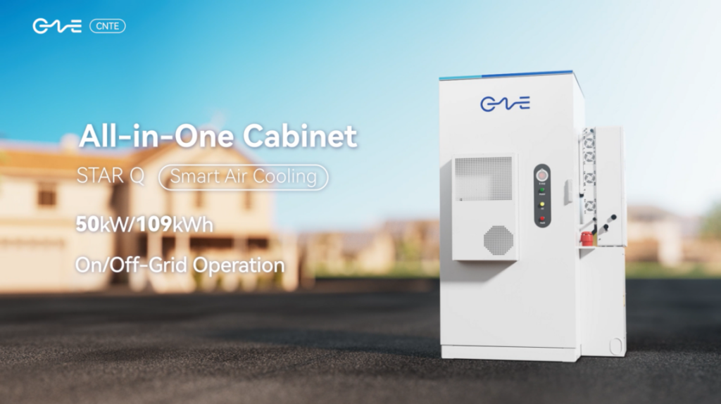
CNTE New Product Launch STAR Q
Jan 15, 2025 -

CNTE Named to Forbes China 2024 Top 30 Go-International Brands
Jul 06, 2026