5 Engineering Factors for Implementing Commercial Solar Storage Units
Modern industrial operations face complex challenges characterized by rising grid tariffs, strict emission mandates, and the necessity for power reliability. While commercial photovoltaic installations offer a clean generation source, their intermittent nature limits their capacity to provide continuous power. To address this mismatch between generation and consumption, commercial and industrial (C&I) facilities are increasingly deploying high-capacity solar storage units. These systems act as the primary balancing mechanism within modern microgrids, translating volatile renewable energy into dispatchable, high-value power assets.
Implementing large-scale energy storage requires a deep understanding of electrochemical properties, system topology, and thermal dynamics. CNTE (Contemporary Nebula Technology Energy Co., Ltd.) specializes in addressing these complex system integration needs, developing utility-scale and C&I energy storage solutions that maintain grid stability and support decentralized power networks. By integrating advanced battery chemistries with intelligent control systems, modern energy assets protect heavy industry from grid fluctuations while maximizing the financial returns of onsite solar generation.

The Current Challenges in Industrial Power Infrastructure
High-demand facilities, such as manufacturing plants, data centers, and logistics hubs, operate under tight operational tolerances. Relying solely on the traditional utility grid presents several vulnerabilities. First, peak demand charges—levied by utilities based on the highest usage registered during a billing cycle—can account for up to 50% of an industrial facility's total electricity bill. Second, voltage sags, swells, and transient interruptions threaten precision manufacturing equipment, where even a millisecond power disruption can result in significant material loss and downtime.
Standard solar arrays cannot resolve these issues independently. When solar generation drops due to cloud cover or seasonal variations, the facility must instantly draw power from the grid, triggering sudden demand spikes. Solar storage units resolve this issue by buffering these fluctuations. These systems absorb excess solar power during peak production periods and discharge it during peak demand intervals, smoothing the load profile and shielding the facility from high utility rates.
Architectural Breakdown of Industrial Solar Storage Units
An industrial-grade energy storage system is not merely a collection of battery cells; it is a highly engineered ecosystem comprising electrochemical storage, power conversion, thermal control, and intelligent management layers.
Electrochemical Cell Chemistry and Degradation Mitigation
The selection of battery chemistry directly influences the system's operational lifespan, safety profile, and levelized cost of storage. Lithium Iron Phosphate (LFP) chemistry has emerged as the industry standard for stationary BESS applications. LFP cells offer a high thermal runaway threshold, excellent cycle life (often exceeding 6,000 cycles at 80% Depth of Discharge), and do not rely on cobalt, which reduces supply chain vulnerabilities.
Managing degradation in LFP cells requires precise control over operational parameters. Factors such as high operating temperatures, sustained high states of charge (SoC), and high charge/discharge rates (C-rates) accelerate the growth of the solid electrolyte interphase (SEI) layer, leading to capacity fade. Modern BESS enclosures utilize advanced cell balancing, both passive and active, to maintain uniform voltage across thousands of series-connected cells, preventing individual cell overstress and extending the aggregate operational life of the asset.
Power Conversion Systems (PCS) and Inverter Topology
The PCS serves as the bidirectional bridge between the direct current (DC) battery bank and the alternating current (AC) facility bus or grid. Modern installations utilize centralized or string inverter topologies depending on system scale and redundancy requirements. centralized systems offer high efficiency and lower initial capital expenditure, while string topologies provide higher system availability and simplified maintenance.
Advanced PCS units operate in multiple modes:
Grid-Following Mode: The inverter synchronizes with the existing grid frequency and voltage, acting as a current source to inject active and reactive power.
Grid-Forming Mode: In islanded operations, the PCS acts as a voltage source, establishing the local grid frequency and voltage, allowing the facility to operate independently during utility outages.
Harmonic Mitigation: Active filtering capabilities within the PCS can inject compensating currents to neutralize harmonics generated by non-linear loads within industrial plants, improving overall power quality.
Thermal Management and Safety Engineering
Thermal consistency is a key factor in preventing localized cell degradation and mitigating safety hazards. Air-cooling systems, while simpler, often struggle to maintain uniform temperatures across dense battery racks, leading to temperature deltas that shorten pack life. Liquid-cooling systems represent a more sophisticated engineering approach, utilizing chilled plates and coolant channels to keep temperature differentials between cells within a tight tolerance (typically under 2°C).
To address thermal runaways, a multi-layer safety strategy is required. This begins at the chemistry level with LFP, progresses through localized electrical isolation (fuses and contactors at the module and rack levels), and extends to advanced sensor arrays that detect off-gassing (such as hydrogen and carbon monoxide) before visible smoke or temperature spikes occur. Integrated clean-agent fire suppression systems are then deployed to neutralize localized incidents before they can propagate to adjacent racks.
Primary Application Scenarios in the C&I Sector
Deploying solar storage units yields diverse operational and financial benefits across different industrial configurations. Understanding these use cases allows engineering teams to size and program systems to meet specific operational goals.
Peak Shaving and Demand Charge Reduction
For most C&I facilities, the primary financial driver for energy storage is peak shaving. By monitoring real-time power consumption at the main utility meter, the energy management system (EMS) triggers the storage system to discharge whenever the load exceeds a predetermined threshold. This caps the facility’s peak demand draw from the utility. By utilizing solar storage units to shave these peaks, enterprises can lower their monthly demand charges without altering their production schedules.
Microgrid Integration and Uninterruptible Power Supply (UPS)
In regions with unreliable utility grids, or for facilities requiring high reliability (such as pharmaceutical manufacturing or semiconductor fabrication), energy storage acts as the core of an onsite microgrid. When combined with solar PV and local diesel generation, the storage system provides a seamless transition during a grid failure. The battery system responds within milliseconds to supply the load, preventing equipment shutdowns, while the microgrid controller coordinates the startup of auxiliary generators if the outage outlasts the battery's reserve capacity.
EV Fleet Charging Integration
As enterprises transition logistics fleets to electric vehicles, the localized power demand at charging depots can easily exceed the capacity of existing grid connections. Upgrading utility substations is often costly and time-consuming. Solar storage units act as local power buffers, charging from solar or off-peak grid power and discharging at high rates to power multi-megawatt EV charging stations. This setup prevents grid overload and avoids the high demand charges associated with simultaneous fleet charging.
Evaluating the Levelized Cost of Storage (LCOS)
Financial feasibility studies for BESS installations must look beyond initial capital expenditure (CAPEX) to evaluate the Levelized Cost of Storage (LCOS). LCOS represents the total cost of energy discharged from the system over its operational lifetime, expressed in USD per megawatt-hour ($/MWh).
The calculation of LCOS incorporates several operational variables:
Round-Trip Efficiency (RTE): The ratio of energy retrieved from the battery to the energy put into it. Higher RTE (typically 85-90% for liquid-cooled LFP systems) minimizes auxiliary losses and conversion waste.
Depth of Discharge (DoD): Operating at lower DoD limits degradation but reduces usable capacity. Finding the right balance between cycle life and daily depth of discharge is key to maximizing lifetime energy throughput.
Auxiliary Loads: The power consumed by HVAC or liquid-cooling systems, controls, and communication modules. Efficient thermal management design minimizes these auxiliary parasitics, lowering the overall LCOS.
CNTE (Contemporary Nebula Technology Energy Co., Ltd.) focuses on lowering LCOS through high-efficiency system integration, balancing thermal management losses with electrochemical preservation to ensure high capacity retention over long operational lifespans.

Engineering Integration and Implementation Path
Successfully integrating a BESS into an existing industrial facility requires a structured engineering approach. The process begins with comprehensive load profiling, analyzing 15-minute interval utility data over at least 12 months to identify peak demand patterns, seasonal variations, and base load profiles. This data is matched against localized solar irradiation profiles to model the optimal size of the solar storage units.
Following system sizing, structural and electrical integration must address local grid interconnection standards (such as IEEE 1547 and UL 1741) and fire safety codes (such as NFPA 855). Integration engineers must ensure that the BESS communicates seamlessly with the plant's existing Supervisory Control and Data Acquisition (SCADA) system via industrial protocols like Modbus TCP or DNP3, enabling unified monitoring, safety shutdowns, and automated demand-response participation.
Frequently Asked Questions
Q1: How do modern solar storage units manage the fire hazards associated with thermal runaway?
A1: Safety in industrial systems is achieved through a multi-tier design. At the cell level, Lithium Iron Phosphate (LFP) chemistry is used due to its high thermal stability. At the system level, continuous monitoring of cell voltage and temperature by the BMS is combined with early-stage off-gas detection sensors. Liquid-cooling systems maintain uniform cell temperatures, preventing localized hotspots. If thermal runaway occurs within a single module, mechanical barriers, thermal isolation, and automated clean-agent fire suppression systems prevent heat propagation to adjacent modules.
Q2: What is the expected operational lifespan of a C&I lithium-ion storage system?
A2: The operational lifespan of high-quality LFP systems typically ranges from 10 to 15 years, corresponding to 6,000 to 8,000 complete charge/discharge cycles, assuming the system is operated within designed thermal and C-rate parameters. Lifespan is defined as the point at which the battery retains 70% to 80% of its original capacity. Advanced thermal management and conservative charge profiles can extend this operational window.
Q3: Can these systems operate completely independently of the utility grid during a prolonged blackout?
A3: Yes. When equipped with a grid-forming inverter and a microgrid controller, the system can operate in "islanded" mode. In this configuration, the battery establishes the voltage and frequency reference for the local network, allowing onsite solar arrays to continue producing power and charging the battery while supplying the facility's critical loads. For multi-day outages, integrating a diesel generator with the solar-plus-storage system ensures uninterrupted operation.
Q4: How does liquid cooling compare to air cooling in industrial storage units?
A4: Liquid cooling uses a closed-loop coolant cycle directly contacting the cell modules, providing superior heat transfer compared to forced air cooling. This design keeps the temperature variance between cells under 2°C, which is difficult to achieve with air cooling in dense configurations. While liquid cooling has a slightly higher initial cost, it reduces auxiliary energy consumption, prevents localized degradation, and extends the overall life of the battery bank, resulting in a lower lifetime cost of storage.
Q5: What grid compliance certifications are required for deploying a BESS in a commercial facility?
A5: BESS installations must comply with strict international standards to ensure safety and grid compatibility. Key standards include UL 9540 (for energy storage systems and equipment), UL 9540A (evaluating thermal runaway fire propagation), IEC 62933 (for electrical energy storage systems), and IEEE 1547 (governing the interconnection of distributed energy resources). Local utility interconnection agreements also dictate specific reactive power support and voltage ride-through capabilities.
Contact Our Engineering Team for Custom Integration Solutions
Implementing utility-scale or C&I energy storage requires rigorous engineering, detailed load analysis, and robust hardware integration. To discuss your facility's power quality needs, load profiles, or integration requirements with an experienced application engineer, please reach out to our technical consulting team. We provide tailored feasibility studies, system modeling, and grid-compliant system architectures to help streamline your energy transition.
For technical inquiries and customized system sizing, please submit a detailed project specification via our professional B2B inquiry channel.
Get in Touch
Recent Posts
-
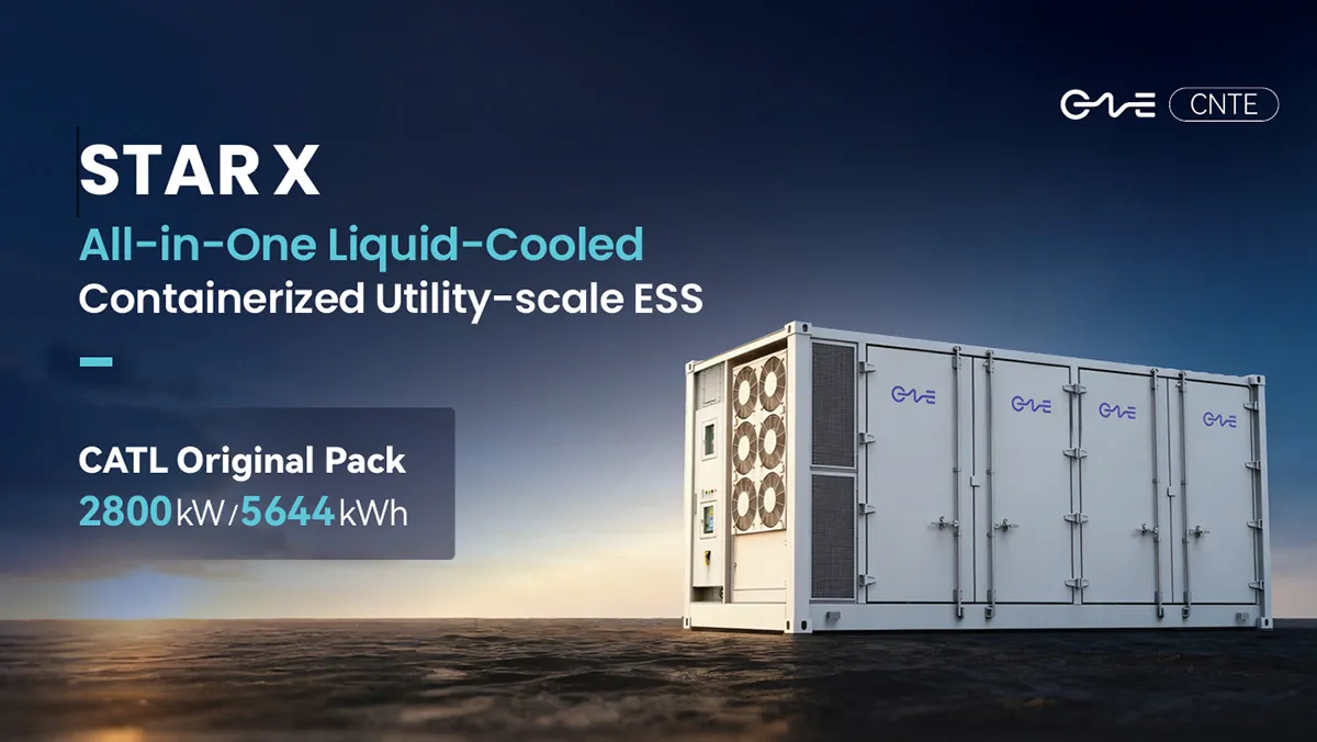
CNTE Launches STAR X Liquid-Cooled DC/AC Integrated Energy Storage System at Intersolar Europe 2026
Jul 06, 2026 -
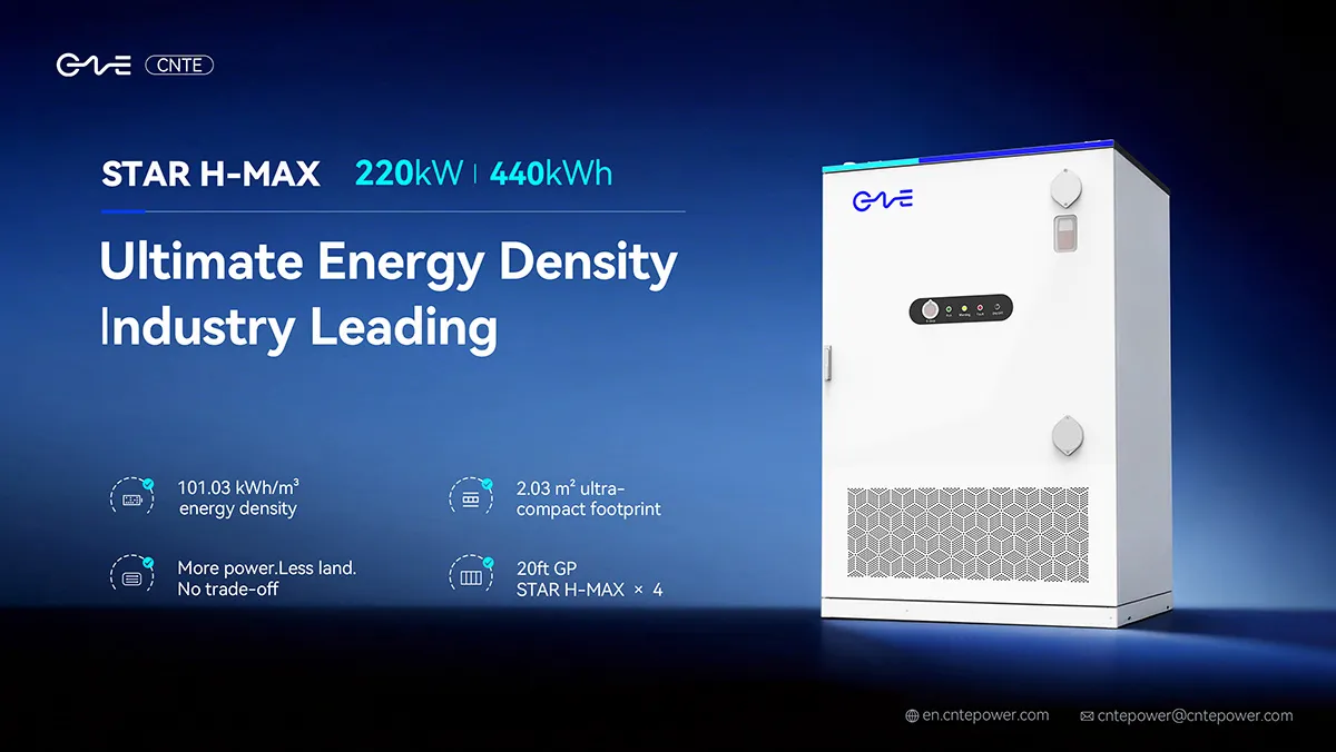
CNTE Unveils New STAR H-MAX Liquid-Cooled C&I ESS at Intersolar Europe 2026
Jun 23, 2026 -
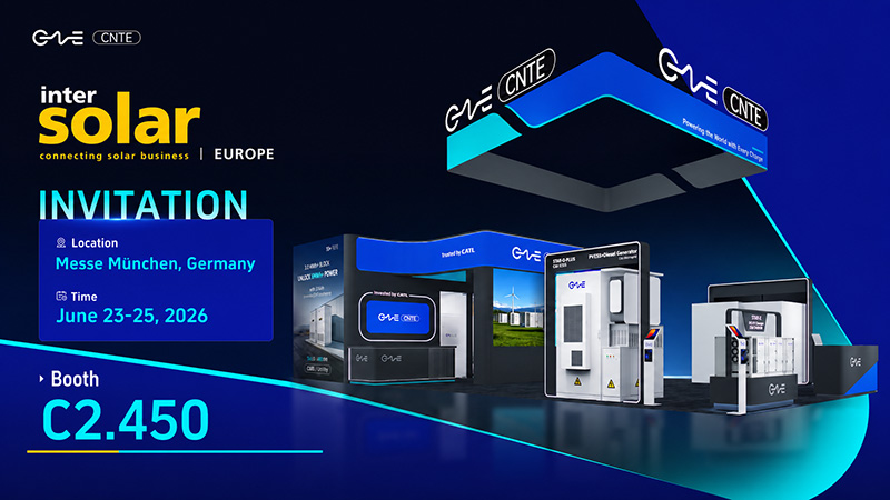
CNTE to Participate in Intersolar Europe 2026
May 20, 2026 -
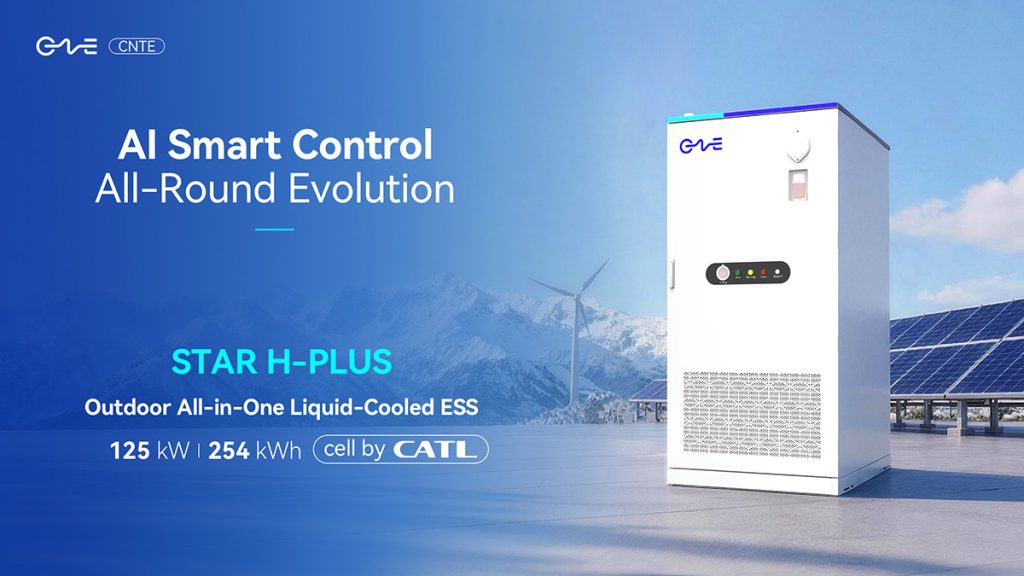
CNTE at KEY ENERGY 2026: Showcases STAR H-PLUS Outdoor Liquid-Cooled Energy Storage System
Mar 05, 2026 -
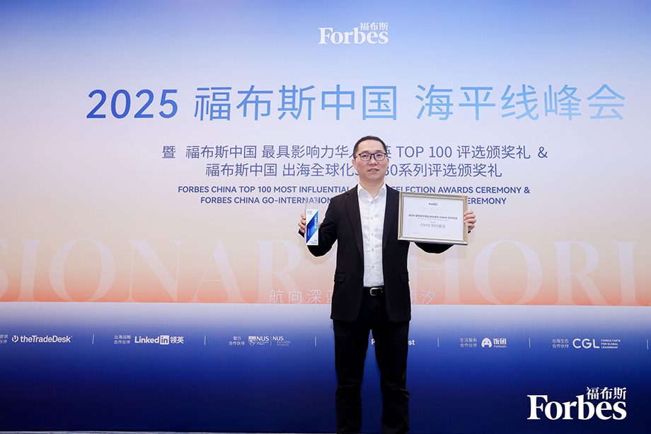
CNTE Honored as 2025 Forbes China Leading Global Brand
Jul 06, 2026 -
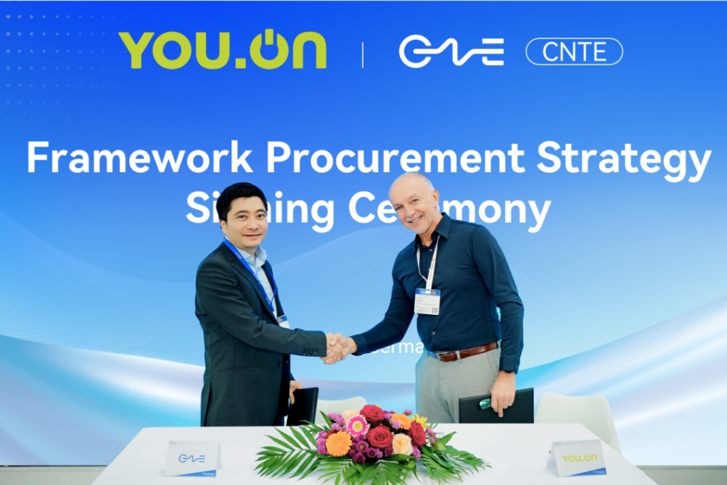
CNTE & YOU.ON Partner to Expand Storage Markets
May 19, 2025 -

CNTE Unveils Energy Storage Lineup at Solartech 2025
May 19, 2025 -
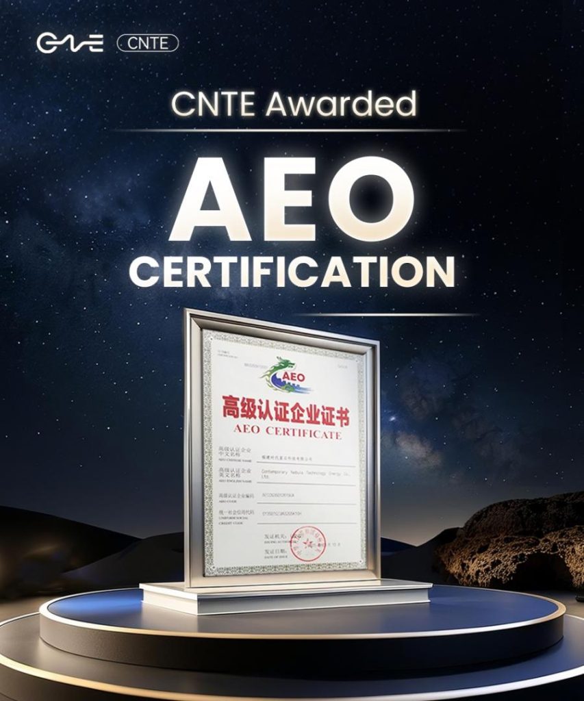
CNTE awarded AEO certification
Jul 06, 2026 -
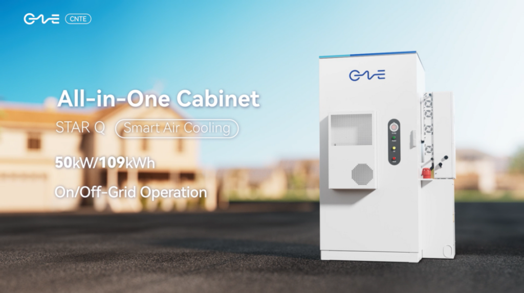
CNTE New Product Launch STAR Q
Jan 15, 2025 -
CNTE Named to Forbes China 2024 Top 30 Go-International Brands
Jul 06, 2026