
Solar System Battery Installation: Design, Safety Codes & CNTE Solutions
The global transition toward decentralized energy management has fundamentally redefined energy storage from a luxury add-on into a core operational asset. As utility tariff structures shift toward dynamic Time-of-Use (TOU) schedules and net-metering compensation rates drop across major markets, integrating energy storage systems (ESS) with photovoltaic (PV) arrays is essential for capturing full financial returns. Achieving optimal performance, long-term safety, and high return on investment requires a thorough understanding of system engineering, regulatory standards, and hardware compatibility during a solar system battery installation.
The Financial and Technical Drivers of On-Site Energy Storage
Adding battery storage to a solar PV infrastructure resolves the core issue of solar generation: the operational misalignment between peak generation hours and peak load demand. Without localized storage, surplus generation is exported back to the grid at wholesale or degraded avoided-cost rates, while peak evening loads are met using expensive utility power.
Time-of-Use (TOU) Arbitrage: Intelligent Battery Management Systems (BMS) automatically store low-cost midday solar generation or low-cost off-peak grid power, discharging it during high-rate evening demand windows.
Mitigation of NEM 3.0 Export Reductions: Under updated utility frameworks like California's NEM 3.0, grid export values have dropped by up to 75%. Storing surplus generation locally preserves the energy's full financial value.
Resilience and Uninterruptible Power Supply (UPS): Grid outages disconnect grid-tied PV inverters due to anti-islanding regulations. A properly commissioned storage system forms a microgrid using an islanding contractor, providing continuous backup power for critical circuits.
Demand Charge Reduction: For commercial setups, high-capacity battery units flatten peak power spikes, substantially lowering utility demand charges on monthly bills.
Technical Topology Comparison: AC-Coupled vs. DC-Coupled Systems
Selecting between an AC-coupled or DC-coupled architecture dictates system efficiency, equipment specifications, total hardware expenditure, and overall installation complexity during a solar system battery installation.
DC-Coupled Architecture
In a DC-coupled configuration, both the PV array and the energy storage array connect to a shared DC bus managed by a single hybrid inverter. Solar power charges the battery bank directly in DC format, requiring only one single conversion step from DC to AC when powering home or building loads.
Round-Trip Efficiency (RTE): High, typically ranging between 95% and 98%, due to minimized conversion stages.
Best Use Case: Ideal for brand-new solar-plus-storage projects where the inverter can be sized and optimized alongside the battery array from day one.
Retrofit Limitations: Requires replacing existing legacy string inverters with a centralized multi-input hybrid inverter, which increases upfront capital costs for existing solar owners.
AC-Coupled Architecture
An AC-coupled system connects the storage battery to the main AC panel via its own dedicated battery inverter. Electricity generated by the PV panels passes through the primary solar inverter to become AC power. To charge the battery, this power undergoes a second conversion back to DC via the battery inverter, and then a third conversion from DC back to AC when powering household loads.
Round-Trip Efficiency (RTE): Moderately lower, ranging between 85% and 90%, due to repeated triple-conversion losses.
Best Use Case: Outstanding for retrofitting established solar installations. It allows the original PV inverter to remain fully operational without altering existing array wiring.
Redundancy Advantage: System failure in either the solar inverter or the battery inverter does not completely shut down power generation from the operational component.
Architecture Performance Matrix
| Technical Metric | AC-Coupled Architecture | DC-Coupled Architecture |
|---|---|---|
| Round-Trip Efficiency (RTE) | 85% – 90% | 95% – 98% |
| Primary Application | Retrofits on existing PV installations | New solar-plus-storage builds |
| Conversion Stages (Solar to Battery) | DC to AC, then AC to DC (2 steps) | Direct DC to DC transfer (1 step) |
| Inverter Architecture | Dual Inverters (PV Inverter + Storage Inverter) | Single Integrated Hybrid Inverter |
| Retrofit Complexity | Low (Standard AC wiring additions) | High (Inverter replacement & rewire) |
Storage Chemistry Evaluation: LFP vs. NMC and Lead-Acid
Energy storage chemistry dictates thermal safety profiles, lifetime cycle count, depth of discharge (DoD) operational limits, and spatial footprint requirements.
Lithium Iron Phosphate (LiFePO4 / LFP): The industry standard for modern stationary energy storage. LFP chemistry offers high thermal runaway thresholds (>270°C), non-toxic chemistry, and cycle lifespans exceeding 6,000 cycles at 80–90% Depth of Discharge. Manufacturers like CNTE (Contemporary Nebula Technology Energy Co., Ltd.) deploy advanced LFP cell design to maximize operational safety, chemical longevity, and thermal stability across diverse environments.
Nickel Manganese Cobalt (NMC): Offers higher energy density per kilogram, making it common in space-constrained electric vehicles. However, it exhibits lower thermal stability than LFP and experiences faster capacity degradation under frequent high-temperature cycling.
Lead-Acid (Flooded/AGM/Gel): An older technology with low upfront unit costs, but constrained by low Depth of Discharge thresholds (50%), short lifespan (500–1,200 cycles), long recharge windows, and mandatory ventilation for off-gassing. They are rarely recommended for modern high-efficiency energy projects.
Voltage Selection and System Phase Requirements
Sizing electrical parameters correctly prevents line losses, voltage drops, and equipment overheating during extended heavy-load operations.
Low Voltage (48V nominal) vs. High Voltage (200V–800V+)
Small residential systems traditionally operate on 48V DC architectures. While safe and easy to scale, lower voltage requires thicker copper cables to handle higher amperage for equal power throughput ($P = V \times I$). Modern commercial and high-capacity residential systems utilize High Voltage (HV) architectures (typically 200V DC to 800V DC). High-voltage battery systems run at significantly lower current, reducing resistive line losses ($I^2R$), optimizing operational efficiency, and allowing the use of thinner, more manageable wiring runs.
Single-Phase vs. Three-Phase Load Balancing
System designers must align output topology with local utility electrical standards:
Single-Phase (Split-Phase 120V/240V): Common in North American residential applications. High-draw continuous loads (e.g., HVAC compressor motors, water pumps) require high surge capacity (LRA – Locked Rotor Amperage) support from the inverter battery combination.
Three-Phase (208V/400V/480V): Standard across commercial buildings and European/Australian residential installations. Three-phase storage installations distribute power evenly across phases to prevent voltage imbalances, transformer overheating, and unexpected phase trip issues during grid outages.
Pre-Installation Compliance, Code Standards, and Thermal Management
A compliant solar system battery installation demands strict adherence to international electrical, fire safety, and structural codes.
Key Regulatory and Safety Standards
NEC Article 706 (USA): Governs Energy Storage Systems (ESS), detailing explicit requirements for disconnect means, overcurrent protection, and system circuit ratings.
UL 9540 & UL 9540A: Standard for Energy Storage Systems and Equipment, with 9540A evaluating large-scale fire propagation testing to ensure runaway events cannot cascade between adjacent battery modules.
NFPA 855: Standard for the Installation of Stationary Energy Storage Systems, enforcing total energy capacity caps (typically 20 kWh per unit enclosure) and minimum operational separation clearances (3 feet/0.9 meters) from walls and openings.
AS/NZS 5139: Australian safety regulations restricting battery placements near habitable rooms, ceiling spaces, egress routes, or non-fire-rated structural walls.
Site Placement and Environmental Engineering
Battery degradation accelerates when operating outside recommended ambient temperature bands (typically 15°C to 30°C for optimal lifespan):
Garage & Utility Room Installs: Offers high protection from direct solar radiation and severe freeze cycles. Structural mounting walls must consist of non-combustible materials (masonry, concrete, or backed cement board).
Outdoor Installations: Requires rugged enclosures with minimum IP65 or NEMA 4X ingress protection ratings to resist rain, humidity, dust, and coastal salt corrosion. Outdoor units should be fitted with heat shields or positioned away from direct sunlight to prevent thermal throttling.
Step-by-Step Execution Protocol for Solar System Battery Installation
System commissioning requires strict execution of electrical and physical protocols by licensed NABCEP-certified technicians or equivalent qualified engineers.
1. Pre-Engineering Site Assessment
Evaluate main distribution board (MDB) busbar ratings and available breaker slots.
Calculate peak instantaneous continuous and surge electrical loads for dedicated backup subpanels.
Verify structural load capacities for wall mounting brackets or floor foundations handling heavy battery weight (often 100–300+ kg).
2. Physical Mounting and Clearance Setup
Anchor structural brackets using expansion bolts on solid masonry walls or heavy-duty lag bolts into structural wall studs.
Enforce mandatory manufacturer separation distances (typically 30 inches / 750 mm clear space in front and 12 inches / 300 mm laterally) for heat dissipation and maintenance access.
3. Electrical Wiring & Overcurrent Protection
Install dedicated rapid DC disconnect switches between the battery bank and inverter.
Route high-voltage DC or AC cables through code-compliant metallic conduits (EMT or flexible liquid-tight conduit).
Connect low-voltage control communications using shielded twisted-pair cables (CAN bus or RS485) to establish real-time data sync between the BMS and inverter hardware.
4. System Commissioning & Testing
Conduct polarity checks, insulation resistance testing (megohmmeter), and continuous ground-fault checks.
Update BMS and inverter firmware to latest operating builds via cloud management interface.
Simulate direct utility grid blackout events to test switchover times, islanding contractor engagement, and subpanel load stability.
Tier-1 Industrial and Residential Solutions from CNTE
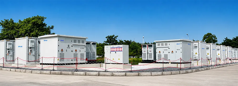
Choosing the right energy storage manufacturer determines whether an installation operates reliably over its multi-decade design life. CNTE (Contemporary Nebula Technology Energy Co., Ltd.) specializes in high-reliability energy storage solutions built on lithium iron phosphate (LFP) chemistry.
CNTE platforms incorporate advanced cell-level thermal monitoring, intelligent internal cell-balancing algorithms, and modular stackability. Built to meet rigorous global standards, CNTE systems support both AC and DC coupling configurations. This ensures seamless integration into residential projects and enterprise-grade commercial sites alike. By delivering high round-trip efficiency, broad ambient operating windows, and long lifecycle endurance, CNTE provides system integrators, EPC contractors, and end users with long-term performance and power security.
Frequently Asked Questions
1. Can a solar system battery installation be retrofitted onto an older solar system?
Yes. Legacy PV systems can be retrofitted using an AC-coupled battery architecture. This configuration adds a battery inverter and energy storage array alongside the existing solar inverter without disturbing the original PV panel string wiring. Alternatively, if the original solar inverter is near the end of its operational lifespan (8-10 years old), replacing it with a centralized hybrid inverter via DC-coupling provides superior efficiency.
2. How long will a solar battery supply backup power during a grid failure?
Runtime depends directly on usable battery capacity (kWh) and real-time power draw (kW). A standard 10 kWh usable capacity LFP battery powering essential critical loads (refrigeration, LED lighting, Wi-Fi, control circuits, totaling 1 kW continuous load) will run for roughly 10 hours. When coupled with ongoing daytime solar generation, the system can sustain critical circuits indefinitely during extended outages.
3. What is the difference between battery power rating (kW) and energy rating (kWh)?
Energy capacity measured in kilowatt-hours (kWh) represents the total volume of electricity stored within the battery pack over time. Power capacity measured in kilowatts (kW) indicates the maximum instantaneous electrical output the battery can deliver at any single moment to start and run electrical loads.
4. Do modern solar batteries require routine maintenance?
Solid-state and LFP lithium-ion storage systems require minimal physical maintenance compared to flooded lead-acid batteries. Key maintenance involves keeping monitoring software updated via active Wi-Fi/Ethernet links, verifying structural bolt tightness, keeping heat-sink cooling vents clear of dust or debris, and periodically inspecting external electrical conduits for thermal or physical wear.
5. How does temperature impact the operational lifespan of installed solar batteries?
Extreme cold reduces momentary usable capacity and slows chemical reaction rates, while extreme ambient heat (>45°C) accelerates internal chemical degradation and reduces total cycle lifetime. Quality installations utilize built-in thermal management systems or locate battery units inside climate-regulated spaces, such as garages or shaded, IP65-rated insulated enclosures.
Accelerate Your Project with CNTE Storage Systems
Are you an EPC contractor, commercial developer, or energy equipment distributor seeking reliable, high-performance energy storage solutions? Build your next project on advanced storage technology designed for maximum safety, thermal stability, and long cycle life. Contact the technical engineering team at CNTE (Contemporary Nebula Technology Energy Co., Ltd.) today to request system specifications, wholesale catalog access, or customized project design quotes.
Get in Touch
Recent Posts
-
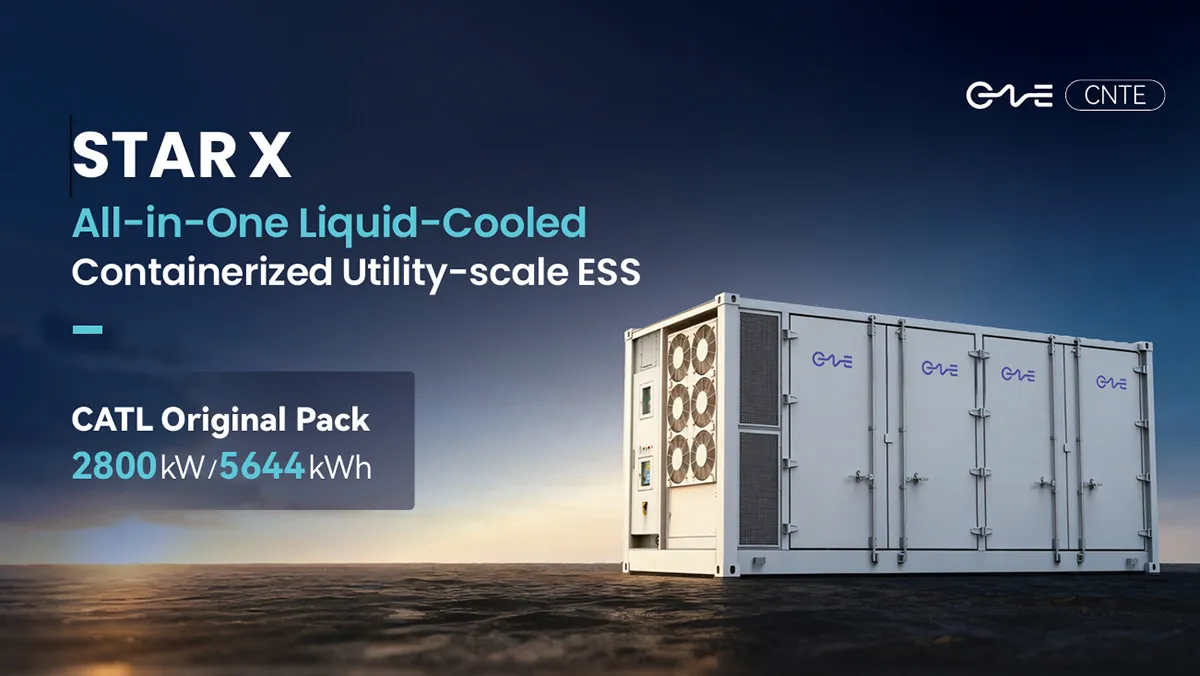
CNTE Launches STAR X Liquid-Cooled DC/AC Integrated Energy Storage System at Intersolar Europe 2026
Jul 06, 2026 -
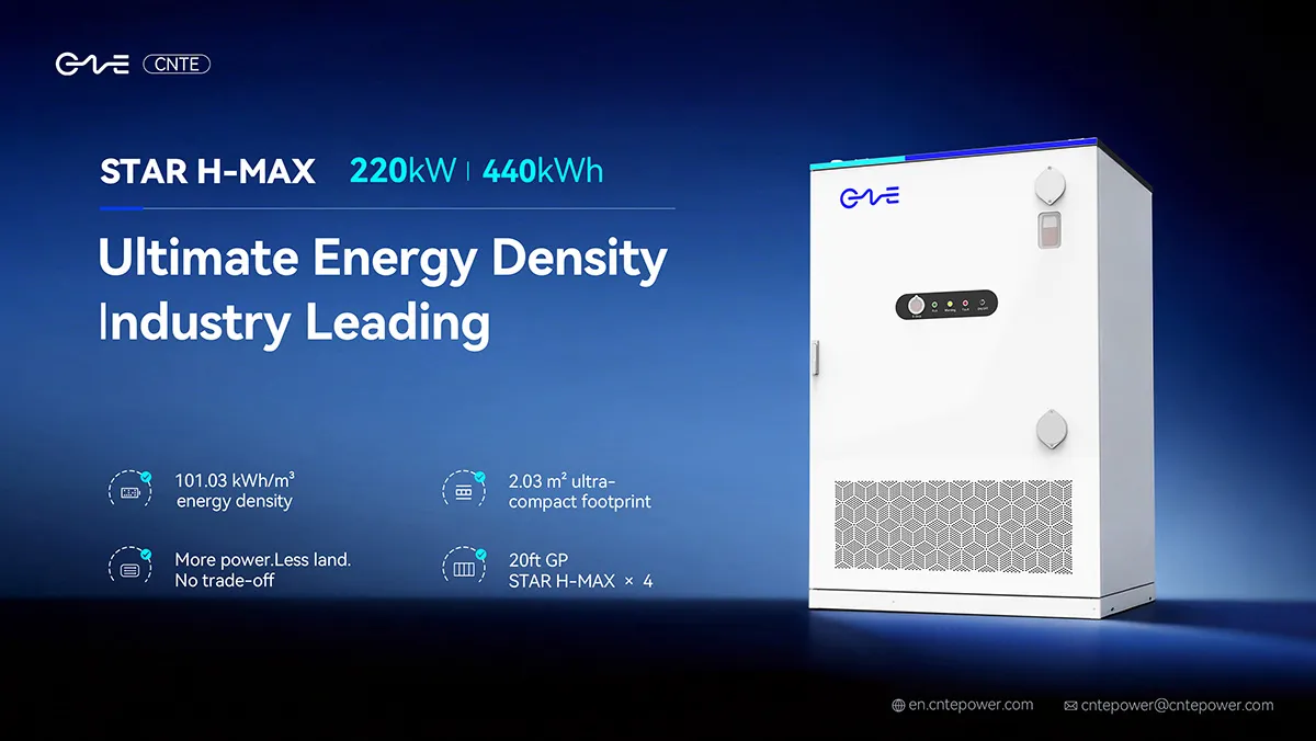
CNTE Unveils New STAR H-MAX Liquid-Cooled C&I ESS at Intersolar Europe 2026
Jun 23, 2026 -
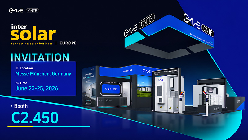
CNTE to Participate in Intersolar Europe 2026
May 20, 2026 -
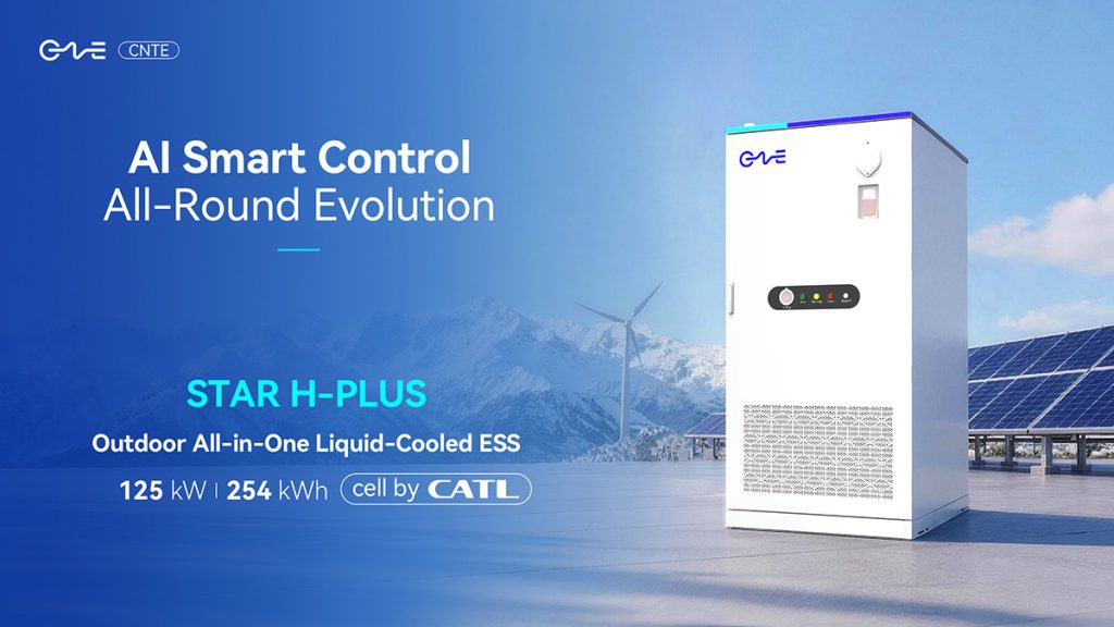
CNTE at KEY ENERGY 2026: Showcases STAR H-PLUS Outdoor Liquid-Cooled Energy Storage System
Mar 05, 2026 -

CNTE Honored as 2025 Forbes China Leading Global Brand
Jul 06, 2026 -

CNTE & YOU.ON Partner to Expand Storage Markets
May 19, 2025 -

CNTE Unveils Energy Storage Lineup at Solartech 2025
May 19, 2025 -
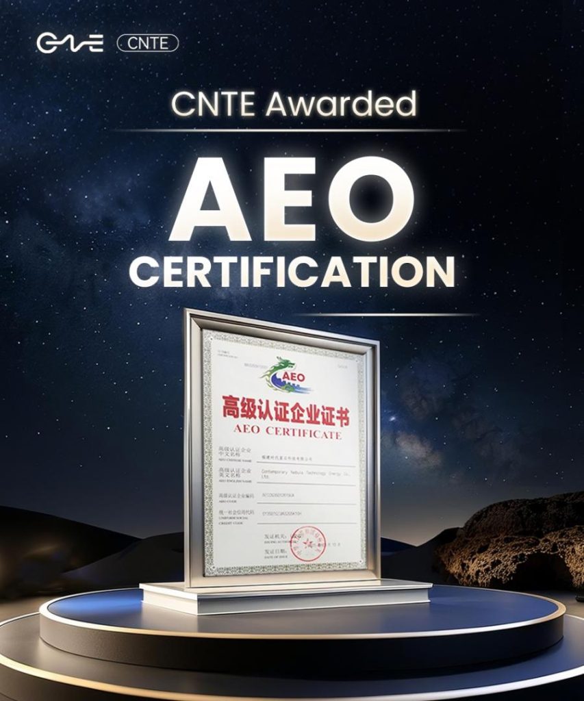
CNTE awarded AEO certification
Jul 06, 2026 -
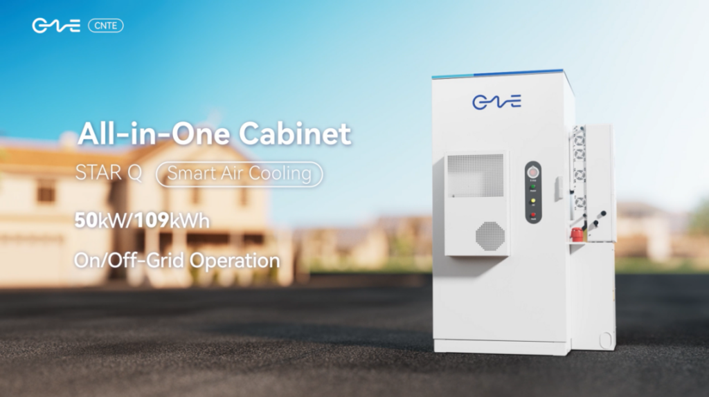
CNTE New Product Launch STAR Q
Jan 15, 2025 -

CNTE Named to Forbes China 2024 Top 30 Go-International Brands
Jul 06, 2026
