How Does an Integrated ESS BESS Address Grid Instability and Demand Charges?
The global transition toward decentralized power generation requires a fundamental restructuring of how energy is stored and distributed. As intermittent renewable sources like solar photovoltaic and wind energy become dominant components of the generation mix, traditional grids face unprecedented stability challenges. Without traditional rotational inertia from fossil-fuel generators, modern grids suffer from rapid frequency variations and power quality degradation. Addressing these challenges requires utility-scale and commercial energy storage systems capable of millisecond-level response times.
Within this framework, the integration of stationary batteries into a comprehensive energy storage system, commonly referred to as an ess bess setup, provides the necessary dispatchability to stabilize modern distribution networks. These systems bridge the gap between volatile generation and dynamic load demands, acting as both load-shaving buffers for heavy industry and ancillary service providers for utility operators. Understanding the engineering parameters, battery chemistries, and control strategies governing these installations is indispensable for modern power infrastructure planning.
Architectural Anatomy of Modern Stationary Storage Systems
An industrial-grade energy storage configuration is not a simple collection of batteries, but a highly integrated multi-layered system. Each layer operates under strict control protocols to ensure system longevity, efficiency, and safety. The primary layers include the battery system, the Battery Management System (BMS), the Power Conversion System (PCS), and the high-level Energy Management System (EMS).
Electrochemical Selection: LFP versus NMC
The choice of battery chemistry dictates the operating parameters, lifetime cost, and safety profile of the entire installation. The two primary chemistries dominating the commercial market are Lithium Iron Phosphate (LFP) and Nickel Manganese Cobalt (NMC).
Lithium Iron Phosphate (LFP): LFP chemistry offers a nominal voltage of 3.2V and is highly favored for stationary applications. Its structural stability during cycling allows for a long lifespan, often exceeding 6,000 to 8,000 cycles at 80% Depth of Discharge (DoD). Furthermore, LFP possesses a high thermal runaway threshold (typically around 270°C), making it inherently safer under mechanical or electrical abuse.
Nickel Manganese Cobalt (NMC): NMC offers higher volumetric and gravimetric energy density, making it suitable for space-constrained installations. However, its lower thermal runaway threshold (approximately 210°C) and shorter cycle life (typically 3,000 to 5,000 cycles) make it less common for large-scale stationary installations where physical footprint is not the primary constraint.
Multi-Level Thermal Management
Battery degradation is highly sensitive to operating temperatures. Operating cells above 40°C accelerates solid electrolyte interphase (SEI) layer growth and capacity loss, while operating below 15°C increases internal resistance and the danger of lithium plating during charging. Consequently, thermal management is a key aspect of system design.
Modern high-capacity configurations utilize active liquid cooling rather than forced-air systems. Liquid cooling plates, containing a water-glycol mixture, run in direct contact with cell surfaces or module bases. This method maintains cell-to-cell temperature deltas within a tight 2°C to 3°C margin, which is crucial for preventing localized cell degradation and minimizing the hazard of thermal runaway propagation. When designing a large-scale project, specifying the configuration of an ess bess requires close attention to these architectural layers to prevent performance bottlenecks.
Power Conversion and Control Systems
The Power Conversion System (PCS) serves as the bidirectional interface between the direct current (DC) battery bank and the alternating current (AC) utility grid. Modern PCS units utilize wide-bandgap semiconductor devices, such as Silicon Carbide (SiC) MOSFETs, to achieve round-trip conversion efficiencies exceeding 98%. These inverters must support advanced grid-forming functions, enabling them to simulate virtual inertia and provide autonomous frequency control without relying on an external grid reference voltage.
Resolving Commercial and Industrial Operational Challenges
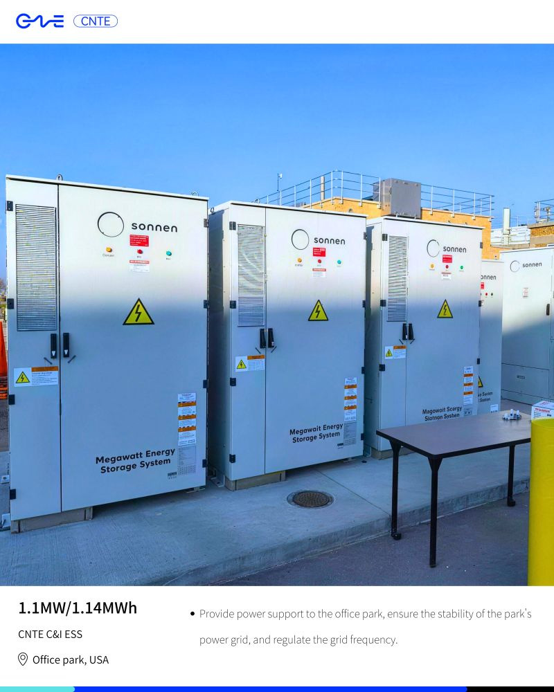
Commercial and Industrial (C&I) facilities encounter severe energy management challenges, driven by rising demand charges, grid instability, and the pressure to reduce carbon footprints. High-demand industries, such as manufacturing, chemical processing, and data centers, face significant operational disruptions when power quality degrades.
Demand Charge Mitigation via Peak Shaving
Utility companies often bill C&I customers using a dual-tariff structure: consumption charges (based on total kilowatt-hours used) and demand charges (based on the highest average power draw during a brief window, typically 15 minutes, within the billing cycle). In some jurisdictions, demand charges can constitute up to 50% of the total monthly electricity bill.
Through peak shaving, the integrated storage system monitors the facility’s main grid connection. When load draw exceeds a predetermined threshold, the system discharges rapidly to supply the excess power locally. When load requirements drop, the batteries recharge from the grid during low-tariff periods or from on-site solar generation, maintaining a flat grid consumption profile.
Improving Power Quality and Microgrid Resilience
Voltage sags, swells, and momentary interruptions can disrupt sensitive manufacturing equipment, leading to expensive downtime and material waste. An on-site battery storage system acts as an active power quality filter, offering continuous voltage regulation and reactive power compensation. In the event of a complete grid failure, the system transitions to island mode within milliseconds, establishing a localized microgrid that maintains operations for crucial processes.
Seamless Transition: Fast-acting static transfer switches disconnect the facility from the utility grid within 2 to 10 milliseconds, preventing voltage drops from resetting computerized systems.
Renewable Integration: On-site solar generation can continue operating within the microgrid, as the storage inverter establishes the reference voltage and absorbs excess generation.
Load Prioritization: The localized EMS can dynamically shed non-critical loads to extend the runtime of vital machinery during extended outages.
Grid-Scale Applications and System Integration
On the utility side of the meter, large-scale storage installations provide services that enhance grid stability, delay expensive infrastructure upgrades, and enable the high penetration of intermittent renewable energy.
To address these challenging demands, systems developed by CNTE (Contemporary Nebula Technology Energy Co., Ltd.) offer robust grid-compliance features, ensuring seamless connection to local utility infrastructure. These systems can execute multiple high-value services simultaneously, maximizing revenue generation and grid support capabilities.
By integrating an advanced ess bess into utility networks, operators can balance load variations without relying on fossil-fuel peaker plants. These services include:
Frequency Regulation: Grid frequency must remain close to nominal values (50 Hz or 60 Hz). Battery systems respond to frequency deviations within milliseconds by absorbing or injecting active power, outperforming traditional gas turbines in speed and accuracy.
Capacity Firming: Solar and wind outputs are subject to sudden drops due to cloud cover or wind fluctuations. A coordinated storage system smooths these transitions, delivering a predictable, constant power curve to the transmission grid.
Black Start Capability: During a total grid collapse, most large power stations require external electricity to restart their auxiliary systems. High-capacity battery systems can energize local transmission lines, providing the initial power required to restart main generation plants.
Safety Engineering and Regulatory Compliance
Given the high energy densities involved, stationary battery safety is a paramount design consideration. Safety cannot be treated as an add-on; it must be engineered into every level of the system architecture, from cell chemistry to structural enclosure design.
Preventing and Managing Thermal Runaway
Thermal runaway occurs when an internal short circuit, mechanical damage, or external heating triggers exothermic chemical reactions within a battery cell. If the heat generation rate exceeds the heat dissipation rate, the cell's temperature rises exponentially, releasing flammable gases and potentially propagating to adjacent cells.
Modern safety designs employ multiple layers of defense to mitigate these hazards:
Cell-Level Safety Devices: Current Interrupt Devices (CIDs) and ceramic-coated separators prevent internal short circuits and disconnect cells under excessive pressure or temperature.
Thermal Barriers: Insulating aerogels or phase-change materials are placed between individual cells within a module to isolate thermal events and prevent propagation.
Advanced Battery Management Systems: High-precision BMS units monitor individual cell voltages and temperatures, employing predictive algorithms to detect micro-short circuits and isolate abnormal modules before thermal runaway occurs.
Leading manufacturers like CNTE (Contemporary Nebula Technology Energy Co., Ltd.) utilize advanced cell-level monitoring to detect early warning signs of thermal anomalies before they escalate. Furthermore, physical enclosures are built to comply with international standards such as UL 9540A, which tests for thermal runaway fire propagation. These enclosures incorporate explosive gas venting, automated fire suppression systems (such as aerosol or clean-agent gases), and integrated water deluge connections for municipal fire department hookups.
Evaluating Lifetime Value and Economic Performance
The financial viability of a large-scale storage installation depends on minimizing the Levelized Cost of Storage (LCOS) and maximizing the system's operational lifetime. Project developers must look beyond initial capital expenditure (CAPEX) to evaluate the total cost of ownership (TCO) over a projected 15- to 20-year operational life.
When calculating long-term operational expenditures, analyzing the degradation curve of an ess bess configuration is a standard procedure for financial stakeholders. System degradation occurs through two primary mechanisms:
Calendar Aging: The natural degradation of battery cells over time, influenced by average storage temperature and state of charge (SoC). Keeping cells at 100% SoC and elevated temperatures accelerates capacity loss.
Cycling Aging: Degradation caused by charge and discharge cycles, influenced by C-rate (the rate of charge/discharge relative to battery capacity) and Depth of Discharge (DoD). High C-rates cause mechanical stress within the electrode materials, leading to micro-cracking and loss of active material.
To maximize financial returns, advanced EMS controllers run intelligent dispatch algorithms that avoid harsh operating states. For example, instead of executing deep, high-power cycles, the software may distribute the load across multiple battery containers or coordinate dispatch times to match cool ambient periods, reducing degradation rates. By maintaining system health, operators can ensure that the facility continues to meet capacity guarantees throughout the duration of its power purchase agreement (PPA).
Frequently Asked Questions
Q1: What is the primary difference between a standard ESS and an integrated ess bess?
A1: An Energy Storage System (ESS) is a broad term encompassing any system capable of storing energy for later use, including mechanical systems (such as pumped-storage hydro or flywheels), thermal systems, and chemical systems. In contrast, an ess bess refers specifically to systems utilizing electrochemical batteries (most commonly Lithium-ion, Flow, or Sodium-ion) as the primary storage medium, integrated with dedicated battery management, power conversion, and thermal control sub-systems.
Q2: Why is liquid cooling preferred over air cooling in large-scale battery installations?
A2: Liquid cooling provides significantly higher heat transfer coefficients compared to air cooling, allowing the system to maintain uniform cell temperatures. Minimizing temperature deltas across the battery pack is critical because even minor temperature variations cause cells to degrade unevenly, reducing the overall capacity and lifespan of the entire system. Liquid systems also require less physical space, allowing for more compact containerized configurations.
Q3: What are the main fire protection standards required for commercial storage installations?
A3: Major international safety standards include UL 1973 (for battery packs in stationary applications), UL 9540 (for the complete energy storage system), and UL 9540A (which evaluates thermal runaway fire propagation). Additionally, systems must comply with local fire codes, such as NFPA 855 in North America, which dictates separation distances, maximum allowable quantities of energy per fire area, and required fire suppression systems.
Q4: How does depth of discharge affect the lifetime of an LFP battery system?
A4: Depth of Discharge (DoD) has a major impact on battery life. Regularly discharging an LFP battery to 100% DoD subjects the electrode structures to higher mechanical stress, which can shorten its overall lifespan compared to shallow cycling (e.g., keeping cycles between 10% and 90% DoD). Most commercial systems are programmed to limit the active operating range to maximize cycle life and improve economic performance over the project's life.
Q5: Can battery storage systems participate in multiple grid programs simultaneously?
A5: Yes, this practice is known as value stacking. An energy storage system can perform demand charge management for an industrial site while simultaneously participating in utility-sponsored programs like frequency response or demand response. However, implementing value stacking requires sophisticated EMS software to manage battery dispatch priorities, ensuring that participating in grid services does not conflict with local operational requirements or accelerate battery degradation excessively.
Commercial Project Inquiry
Developing a robust, utility-scale or commercial-grade energy storage solution requires rigorous engineering, precise system sizing, and strict adherence to international safety regulations. Every facility presents unique load profiles, environmental conditions, and utility interconnection challenges.
For comprehensive design support, system specifications, or feasibility studies regarding your upcoming infrastructure developments, please submit an inquiry to our engineering and consulting team at CNTE (Contemporary Nebula Technology Energy Co., Ltd.). Our team is prepared to assist in optimizing system parameters to match your specific performance metrics and operational goals.
Get in Touch
Recent Posts
-
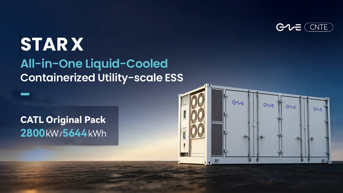
CNTE Launches STAR X Liquid-Cooled DC/AC Integrated Energy Storage System at Intersolar Europe 2026
Jul 06, 2026 -
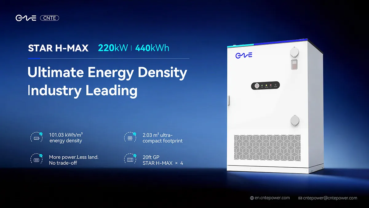
CNTE Unveils New STAR H-MAX Liquid-Cooled C&I ESS at Intersolar Europe 2026
Jun 23, 2026 -
CNTE to Participate in Intersolar Europe 2026
May 20, 2026 -
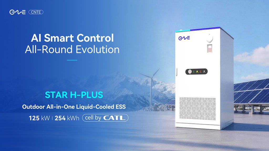
CNTE at KEY ENERGY 2026: Showcases STAR H-PLUS Outdoor Liquid-Cooled Energy Storage System
Mar 05, 2026 -

CNTE Honored as 2025 Forbes China Leading Global Brand
Jul 06, 2026 -

CNTE & YOU.ON Partner to Expand Storage Markets
May 19, 2025 -

CNTE Unveils Energy Storage Lineup at Solartech 2025
May 19, 2025 -
CNTE awarded AEO certification
Jul 06, 2026 -
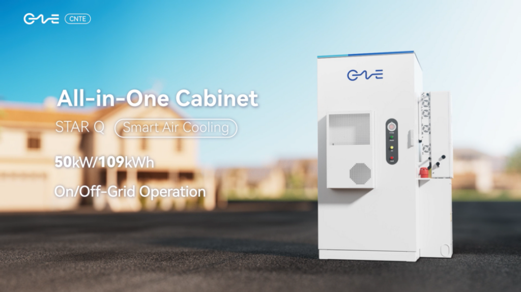
CNTE New Product Launch STAR Q
Jan 15, 2025 -
CNTE Named to Forbes China 2024 Top 30 Go-International Brands
Jul 06, 2026