How Do Modern Solar Power Storage Solutions Address Grid Volatility and Demand Charges?
The integration of renewable energy sources into commercial and industrial grid infrastructures presents significant operational challenges. Solar generation is inherently variable, characterized by supply-demand mismatches, peak generation during low-load periods, and rapid ramp-rate fluctuations. To mitigate these generation anomalies and maintain grid stability, implementing robust solar power storage solutions has transitioned from an operational option to an engineering necessity. This analysis examines the system architecture, thermal management protocols, and economic dispatch strategies that define modern energy storage systems (ESS).
1. System Architecture and Electrochemical Composition
The operational efficiency of modern solar power storage solutions depends heavily on the integration of electrochemical cells, battery management systems, and power conversion topologies. Selecting the appropriate chemistry and hardware configuration determines the lifecycle performance and degradation profile of the installation.
Electrochemical Chemistry Selection
While various battery chemistries exist, Lithium Iron Phosphate (LiFePO4 or LFP) has become the industry standard for stationary B2B storage applications. The preference for LFP over Lithium Nickel Manganese Cobalt Oxide (NMC) is driven by several factors:
Thermal Stability: LFP cells exhibit a higher thermal runaway threshold (approximately 270°C) compared to NMC cells (approximately 210°C), reducing the likelihood of cascading thermal events.
Operational Lifespan: LFP configurations regularly deliver between 6,000 and 8,000 cycles at an 80% Depth of Discharge (DoD) before capacity degrades to 80% of its original rating.
Resource Sustainability: The absence of cobalt and nickel minimizes supply chain vulnerabilities and aligns with corporate environmental compliance metrics.
Power Conversion Systems (PCS) and Inverter Topology
The PCS manages the bi-directional flow of energy between the battery array, the photovoltaic (PV) generators, and the local facility grid. Contemporary system designers choose between centralized and string inverter topologies based on system capacity and site layout:
Centralized Inverter Systems: Best suited for large-scale utility installations. They offer high efficiency at full load, simplified maintenance points, and lower initial capital cost per megawatt. However, they lack granular control at the individual string level, which can lead to mismatch losses if partial shading occurs.
String Inverter Systems: Distributed PCS architectures allow for independent Maximum Power Point Tracking (MPPT) across different battery racks or solar strings. This design increases system redundancy; if one inverter fails, only a fraction of the system capacity is offline.
Advanced system architectures proposed by CNTE (Contemporary Nebula Technology Energy Co., Ltd.) utilize advanced modular PCS units that allow hot-swapping during active operation, minimizing system downtime and maintaining high availability factors for C&I applications.
2. Thermal Management and Degradation Mitigation
Temperature control is a major factor in determining the operational lifetime and safety profile of electrochemical storage systems. Battery degradation accelerates exponentially when operating outside the optimal range of 15°C to 25°C.
Air Cooling versus Liquid Cooling Topologies
Traditional air-cooling systems rely on forced convection via HVAC units. While cost-effective to install, air cooling often leads to localized thermal gradients within the battery enclosure, where cells closer to the exhaust operate at higher temperatures than those near the intake. This uneven temperature distribution causes uneven cell aging, resulting in premature capacity loss for the entire pack.
To resolve this, modern industrial systems utilize closed-loop liquid cooling. In these setups, manufacturers such as CNTE (Contemporary Nebula Technology Energy Co., Ltd.) integrate liquid-cooling plates directly adjacent to the battery cells. This design provides several distinct advantages:
Uniform Temperature Distribution: Liquid cooling maintains cell-to-cell temperature differentials within ±2°C across the entire battery rack, ensuring uniform aging.
Parasitic Load Reduction: Liquid cooling systems consume up to 30% less auxiliary power compared to high-capacity HVAC air systems under high ambient operating conditions, improving round-trip efficiency (RTE).
Physical Compactness: Liquid-cooled systems require less physical space, allowing for higher energy density per square meter of footprint.
State of Charge (SoC) and State of Health (SoH) Management
The Battery Management System (BMS) continuously monitors operational parameters to prevent accelerated degradation. Key functions include active cell balancing—where energy is transferred from higher-voltage cells to lower-voltage cells during charge cycles—and dynamic charge-current throttling based on real-time temperature telemetry. Preventing prolonged exposure to extreme SoC levels (above 95% or below 5%) is crucial for mitigating lithium plating and mechanical stress within the cell electrodes.
3. Commercial and Industrial Application Scenarios
Deploying commercial solar power storage solutions allows enterprises to transition from passive energy consumers to active managers of their electrical demand profiles. This transition offers several financial and operational advantages.
Comparison of C&I Operational Strategies
| Operational Strategy | Primary Mechanism | Primary Financial/Operational Benefit |
|---|---|---|
| Peak Shaving | Discharging during periods of maximum facility demand. | Reduces utility demand charges and peak tariff rates. |
| Load Shifting | Storing low-cost off-peak solar/grid energy for on-peak use. | Arbitrages energy price differentials. |
| Microgrid Backup | Islanding the facility from the grid during outages. | Ensures continuous operation for production lines and data centers. |
| Power Quality Support | Providing rapid reactive power injection. | Mitigates voltage sags and maintains frequency stability. |
Peak Shaving Mechanics
In many jurisdictions, commercial electricity tariffs include a significant demand charge based on the highest average power consumption recorded during a billing cycle (typically measured in 15-minute intervals). By monitoring facility load at the main utility meter, the Energy Management System (EMS) can automatically trigger battery discharge when the load exceeds a predetermined threshold. This limits peak demand and lowers monthly utility expenses.
Microgrid Integration and Islanding Mode
For facilities where power interruptions lead to significant financial loss, integrating storage with on-site solar arrays creates a resilient microgrid. In the event of a grid outage, the PCS performs a black-start sequence, establishing a localized grid reference voltage. The system transitions into islanding mode, decoupling from the main utility grid while managing local load demands using solar generation and stored battery reserves.
4. Grid-Scale Integration and Ancillary Services
Beyond localized commercial applications, utility-scale solar power storage solutions stabilize the network by offering ancillary services to Transmission System Operators (TSOs) and Distribution System Operators (DSOs).
Frequency Containment and Regulation
Grid frequency must be maintained within strict tolerances (e.g., 50 Hz ±0.1 Hz in Europe, 60 Hz in North America) to prevent equipment damage and network instability. When generation exceeds load, frequency rises; when load exceeds generation, frequency drops. Battery storage systems, with response times under 100 milliseconds, are ideal for primary frequency response (Frequency Containment Reserve). The system rapidly absorbs active power from the grid during over-frequency events and injects power during under-frequency events.
Capacity Firming and Ramp-Rate Control
Large-scale solar installations can experience sudden changes in power output due to passing cloud cover. These rapid variations can cause voltage fluctuations at the point of common coupling (PCC). Integrating an ESS allows for active ramp-rate control, smoothing out output fluctuations by storing or releasing power to match a target ramp rate (e.g., limiting changes to 1 MW/minute).
5. Safety Engineering and Hazard Prevention
Large-scale energy storage installations contain significant energy density, requiring rigorous safety systems to prevent operational anomalies and protect surrounding infrastructure.
The safety engineering of solar power storage solutions involves multi-tiered protection architectures. Modern systems utilize a layered defense strategy:
Level 1: Electrochemical Prevention. Using LFP chemistry reduces thermal runaway susceptibility compared to other lithium chemistries.
Level 2: Electrical Safeguards. Fast-acting fuses, contactors, and circuit breakers at the module, rack, and container levels isolate electrical faults before they cause high currents or heat generation.
Level 3: Early-Stage Off-Gas Detection. Before thermal runaway occurs, cells release trace amounts of carbon monoxide (CO), hydrogen (H2), and volatile organic compounds (VOCs). Installing specialized off-gas sensors allows the system to shut down and isolate affected racks before any visible smoke or heat is detected.
Level 4: Fire Suppression. If temperature thresholds are exceeded, targeted fire suppression systems are activated. These typically use clean-agent gas (such as FK-5-1-12 or Novec 1230) to extinguish flame sources without damaging nearby electrical components.
6. Frequently Asked Questions
Q1: What is the expected cycle life of commercial solar power storage solutions, and how is degradation managed?
A1: Commercial storage systems using LFP chemistry generally achieve between 6,000 and 8,000 cycles at 80% Depth of Discharge (DoD) before capacity drops to 80% of its initial value. This lifespan is maintained by the Battery Management System (BMS), which balances cell voltages, limits temperature variations to within ±2°C using liquid cooling, and manages charge rates based on real-time cell conditions.
Q2: How does liquid cooling compare to HVAC air cooling in high-density battery enclosures?
A2: Liquid cooling provides direct thermal contact with battery cells via cooling plates, maintaining temperature variations across the system within ±2°C. Air cooling relies on forced convection, which often creates temperature gradients, leading to uneven cell aging. Additionally, liquid cooling systems can reduce auxiliary power consumption by up to 30% in high ambient temperatures, improving overall round-trip efficiency.
Q3: Can these storage systems operate during a complete utility grid failure?
A3: Yes. When configured with a bi-directional PCS capable of grid-forming operation, the system can decouple from the utility grid during an outage. It enters islanding mode, establishing a local voltage and frequency reference that allows the facility to continue running on a combination of active solar generation and battery storage.
Q4: What are the primary factors that determine the Levelized Cost of Storage (LCOS)?
A4: LCOS is determined by several factors, including initial capital expenditure (CAPEX) for the batteries and PCS, balance-of-plant costs, round-trip efficiency (RTE), depth of discharge (DoD) limits, maintenance costs (OPEX), and the system's operational cycle life. Minimizing auxiliary power usage via efficient liquid cooling helps lower LCOS by preserving usable energy.
Q5: What safety standards must industrial energy storage installations comply with?
A5: Industrial installations must adhere to strict international safety standards, including UL 9540 (for energy storage systems and equipment), UL 9540A (testing for evaluating thermal runaway fire propagation), IEC 62619 (safety requirements for secondary lithium cells and batteries), and local NFPA 855 standards for the installation of stationary energy storage systems.
7. Consultation and Project Engineering
Designing and deploying commercial-scale solar power storage solutions requires detailed engineering, load profile analysis, and system integration. Selecting the correct battery chemistry, sizing the power conversion system, and implementing effective thermal management are crucial steps to achieving long-term performance and high return on investment.
Collaborating with CNTE (Contemporary Nebula Technology Energy Co., Ltd.) provides access to engineered energy storage hardware designed for commercial, industrial, and utility applications. To discuss system specifications, project modeling, and procurement requirements for your upcoming project, please contact our engineering and sales team for a formal consultation.
Get in Touch
Recent Posts
-
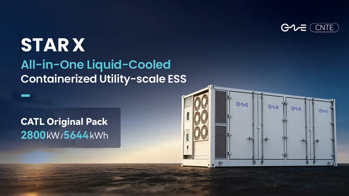
CNTE Launches STAR X Liquid-Cooled DC/AC Integrated Energy Storage System at Intersolar Europe 2026
Jul 06, 2026 -
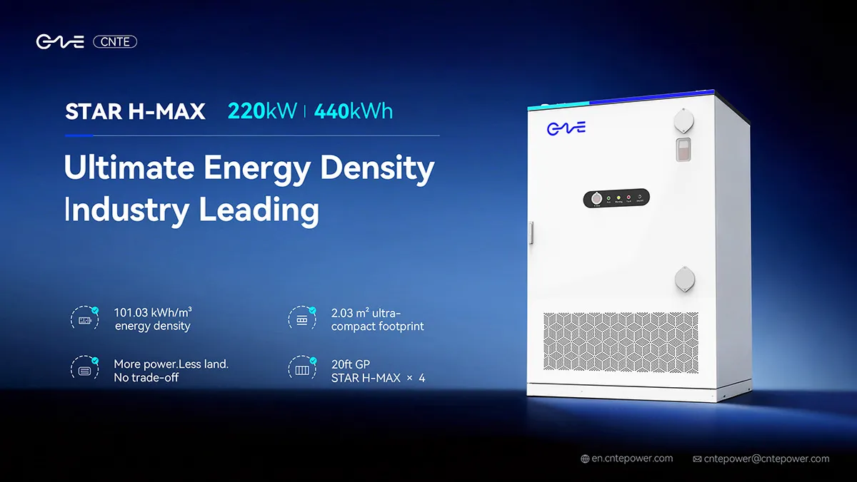
CNTE Unveils New STAR H-MAX Liquid-Cooled C&I ESS at Intersolar Europe 2026
Jun 23, 2026 -
CNTE to Participate in Intersolar Europe 2026
May 20, 2026 -
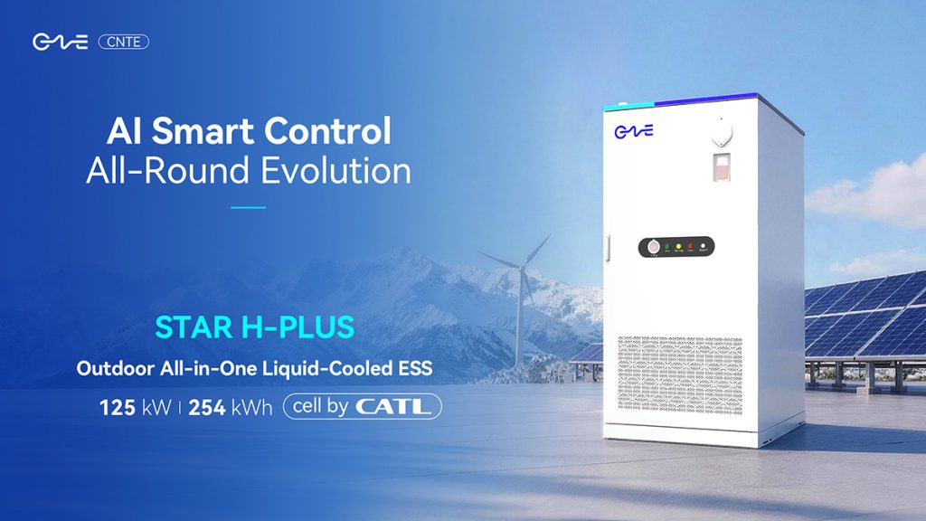
CNTE at KEY ENERGY 2026: Showcases STAR H-PLUS Outdoor Liquid-Cooled Energy Storage System
Mar 05, 2026 -

CNTE Honored as 2025 Forbes China Leading Global Brand
Jul 06, 2026 -

CNTE & YOU.ON Partner to Expand Storage Markets
May 19, 2025 -

CNTE Unveils Energy Storage Lineup at Solartech 2025
May 19, 2025 -
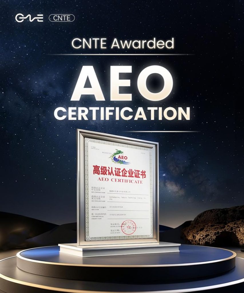
CNTE awarded AEO certification
Jul 06, 2026 -
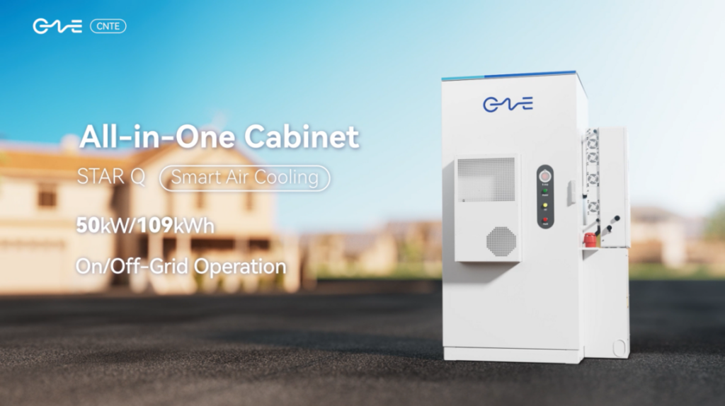
CNTE New Product Launch STAR Q
Jan 15, 2025 -
CNTE Named to Forbes China 2024 Top 30 Go-International Brands
Jul 06, 2026