
High-Performance PCS BESS Solutions: A Technical Guide to Utility & C&I Storage
The transition toward decarbonized power grids relies heavily on the technical synergy between electrochemical storage and advanced power electronics. At the core of this infrastructure sits the bidirectional power conversion system paired with electrochemical cells. Designing a modern utility-scale or commercial and industrial (C&I) pcs bess requires deep comprehension of electromagnetic physics, semiconductor capabilities, thermodynamic stability, and evolving grid codes.
Energy storage components no longer serve merely as passive backup reservoirs. Modern generation-side and transmission-level deployments demand that power conversion subsystems act as fast-responding network stabilizers capable of four-quadrant operation, synthetic inertia injection, and microsecond-level fault clearance. The design choices made at the power electronics stage directly determine round-trip efficiency (RTE), operational longevity, and economic viability over decades of continuous cycling.
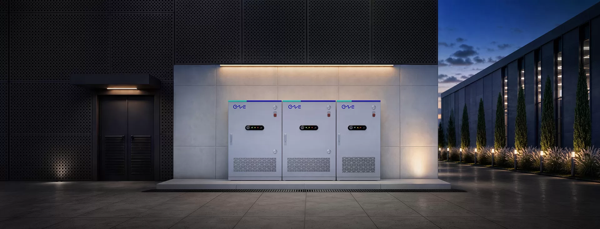
The Bi-Directional Bridge: Fundamental Mechanics of the PCS BESS
A power conversion system functions as the neurological and electrodynamic interface between direct current (DC) battery chemistry and alternating current (AC) high-voltage distribution networks. Within a pcs bess, the conversion stage governs bidirectional electricity pathways: converting AC grid electricity to regulated DC during charging, and converting DC chemical potential back to synchronized, harmonic-free AC power during discharge.
This process demands precise digital signal processors (DSPs) and field-programmable gate arrays (FPGAs) running pulse-width modulation (PWM) or space vector pulse-width modulation (SVPWM) routines. The primary engineering goal is minimizing total harmonic distortion (THD) below 3% while keeping switching losses negligible. Energy losses within the conversion stage appear directly as operational heat, degrading system performance and increasing auxiliary cooling loads across large battery arrays.
Modern system layouts incorporate wide bandgap (WBG) semiconductors, particularly Silicon Carbide (SiC) MOSFETs alongside traditional Insulated Gate Bipolar Transistors (IGBTs). SiC components operate at elevated switching frequencies with lower conduction losses, enabling a smaller footprint for magnetic components like inductors and isolation transformers. Higher operational frequencies translate directly into compact enclosure designs, higher power densities, and faster response times to anomalous system spikes.
Topological Evolution: Centralized, String, and Modular Architectures
Determining the physical and electrical topology of an energy storage installation defines its ongoing maintenance schedule, systemic availability, and capital allocation.
Centralized Topologies: Historically dominant in utility-scale assets, centralized converters route massive DC collection lines from numerous battery racks into a single multi-megawatt inverter stage (typically 1 MW to 4 MW). While offering lower initial capital expenditure per megawatt, centralized conversion creates vulnerability to single-point operational interruptions. If the primary converter faults, the entire associated battery cluster disconnects from dispatch. Furthermore, rack-to-rack mismatch within large DC configurations produces parasitic circulating currents, accelerating cell degradation in weaker modules.
String Architectures: Borrowing design paradigms from utility photovoltaic configurations, string conversion assigns discrete, lower-capacity inverters (typically 100 kW to 250 kW) to individual battery racks or smaller series groups. String systems eliminate rack-to-rack DC interaction, drastically curbing mismatch losses. When a single converter unit requires servicing, the remainder of the plant continues full commercial dispatch. The trade-off involves higher component counts and more communication nodes to coordinate.
Modular Distributed Subsystems: Advanced platforms, such as those refined by CNTE (Contemporary Nebula Technology Energy Co., Ltd.), bridge the advantages of centralized operational control and distributed string maintenance. By utilizing parallel modular conversion trays within centralized enclosures, developers preserve multi-megawatt grid interconnects while retaining the granularity to bypass individual failing conversion stages without shutting down the facility.
Operating voltages present another decisive split. The international market has largely transitioned from legacy 1000V DC bus rails to 1500V DC topologies. Raising systemic operational voltage reduces I²R resistive cable losses throughout the DC field, cuts conductor cross-sectional requirements, and enhances conversion efficiency by approximately 1.5% to 2%. System engineering at 1500V requires stringent insulation coordination, rigorous air clearance engineering, and sophisticated arc-flash mitigation protocols.
Grid Interconnection Mechanics: Grid-Following vs. Grid-Forming Control
Power conversion systems manage the boundary where mechanical grid inertia meets solid-state electrical controls. In legacy configurations, converters operate almost universally in grid-following (GFL) mode. A GFL setup relies on a Phase-Locked Loop (PLL) to measure the fundamental frequency and voltage vector of the external transmission line, subsequently injecting current synchronized to that measured reference angle.
As synchronous thermal power plants retire, the short-circuit ratio (SCR) of regional grids decreases, resulting in weak grid scenarios where conventional PLL algorithms lose lock and destabilize. To address structural network fragility, leading engineering bodies now mandate grid-forming (GFM) capabilities within high-penetration renewable interconnections. A GFM-capable pcs bess functions not as a follower, but as an independent, regulated voltage source behind an internal impedance.
Grid-forming converters employ Virtual Synchronous Generator (VSG) or droop-control algorithms. These routines simulate the physical rotational inertia of heavy turbines directly inside the digital control loops of the solid-state inverter. When transmission-level contingencies drop system frequency, a GFM system automatically releases stored electrochemical energy in the sub-millisecond timeframe, counteracting frequency deviation rate (RoCoF) without waiting for supervisory SCADA instructions.
Beyond synthetic inertia, GFM capabilities provide black-start functionality. In the event of a total regional blackout, the inverter can energize auxiliary station loads, establish reference voltages, and coordinate the sequential re-energization of downstream transmission lines and transformer banks without an external grid signal.
Thermal Dissipation Strategies and Component Reliability
The lifespan of a converter is inextricably linked to the thermodynamic behavior of its power switches and passive magnetic elements. Power modules undergo continuous thermal cycling: rapid heating during dispatch transitions followed by cooling during low-utilization idle states. This cycling imposes shear stresses across copper-substrate solder joints and silicon wire bonds, serving as a primary driver of operational failures.
Air-cooling topologies have dominated utility fields for decades, drawing ambient air through louvers, particulate filters, and heat sinks. Ambient air, however, lacks sufficient thermal capacity in high-ambient environments like deserts or industrialized coastal zones. Particulate accumulation, salt spray, and uneven air velocity profiles across IGBT heat sinks create localized hot spots, prompting converters to derate active power output precisely when grid pricing peaks.
Liquid cooling has emerged as the definitive engineering solution for high-density environments. Liquid-chilled plates mounted directly beneath power semiconductors remove thermal energy with significantly greater heat transfer coefficients than forced air. Maintaining IGBT junction temperatures within narrow, stabilized bands dampens thermal mechanical stress, suppresses silicon aging, and enables true outdoor IP65- or IP66-rated sealed enclosures that protect sensitive driver boards from atmospheric moisture and dust ingress.
Industry-leading architectures deployed by CNTE (Contemporary Nebula Technology Energy Co., Ltd.) demonstrate that pairing liquid-cooled battery blocks with closely coupled liquid-cooled power electronics significantly harmonizes auxiliary energy requirements. By leveraging shared or optimized cooling loops, the auxiliary balance of plant (BOP) parasitic consumption drops, yielding a net increase in long-term facility round-trip efficiency.
Integration Dynamics: DC-Coupled vs. AC-Coupled System Architectures
Designing a utility-scale or microgrid installation requires choosing where renewable generation and energy storage converge electrically. The evaluation between direct current (DC) coupling and alternating current (AC) coupling dictates performance metrics, round-trip losses, and brownfield installation viability.
In DC-coupled setups, both renewable sources (such as solar photovoltaic strings) and the electrochemical array share a unified internal DC bus, connecting to the utility line through a shared bidirectional converter. Power routed from the solar panels directly charges the battery without intermediate conversions, bypassing consecutive DC-AC and AC-DC inverter losses. This topology reduces the footprint of high-voltage transformers and simplifies utility interconnection applications by consolidating output down to a singular grid-tied injection point.
AC-coupled systems, conversely, isolate the solar generation and the battery storage onto separate converters that tie into a common AC collector line. While adding converter units, AC coupling presents exceptional engineering flexibility, especially for brownfield retrofits of existing renewable assets. An AC-coupled pcs bess can be dropped into an operational substation without redesigning existing solar string combiners or interfering with established solar inverter warranties. Each subsystem operates on fully decoupled firmware, simplifying commissioning, diagnostic routines, and multi-vendor component replacements.
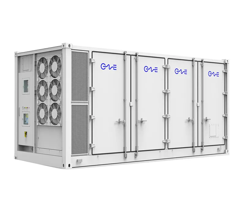
Revenue Optimization via Multi-Quadrant Conversion Operations
The economic justification for an energy storage asset rests upon the agility of its power electronics. Power conversion systems must be engineered to deliver complex, multi-quadrant active and reactive power profiles (P-Q plane) dynamically.
Four-quadrant operation enables the converter to import or export active power while simultaneously generating or absorbing reactive power (capacitive or inductive). During midday hours, high solar penetration can push line voltages beyond statutory bounds. A modern converter can absorb inductive reactive power (+Q) to suppress overvoltage conditions across regional lines, while concurrently charging its DC battery modules (-P) from excess solar generation.
Advanced converter control systems facilitate revenue stacking via automated sub-second operational switching:
Frequency Regulation (FCR/aFRR): Immediate dynamic tracking of system frequency variations, operating under tight response times (< 1 second) to provide immediate frequency stabilization.
Capacity Firming and Peak Shaving: Leveling out unpredictable renewable ramp rates to deliver flat, dispatchable blocks of energy that meet rigid day-ahead market commitments.
Harmonic Mitigation and Active Filtering: Detecting localized non-linear harmonic loads caused by heavy industrial machinery and injecting anti-phase harmonic currents to purify grid power quality.
Arbitrage and Dynamic Dispatch: Storing off-peak, low-value wholesale energy and dispatching it during periods of scarcity pricing, governed by real-time algorithmic energy trading interfaces.
Frequently Asked Questions (FAQ)
What is the core engineering difference between a standard solar inverter and a PCS in an energy storage system?
A conventional solar inverter operates strictly in a unidirectional mode, converting DC power harvested from photovoltaic modules into synchronized AC grid power. A converter within an energy storage configuration is strictly bidirectional, engineered to both invert DC to AC during discharge and rectify AC to DC during charging. Energy storage conversion hardware incorporates bi-directional IGBT/SiC stages, symmetrical thermal management circuits, and bidirectional synchronization controls capable of managing erratic battery voltage variations across varying states of charge (SoC).
How does a 1500V system architecture reduce Total Cost of Ownership (TCO) compared to a 1000V architecture?
Operating an energy storage installation at 1500V DC increases current-carrying capacity for a given conductor cross-section. Higher voltage allows for longer battery strings, fewer parallel connections, and a reduction in total combiner boxes and DC balance-of-plant cabling. Lower operating currents translate to reduced resistive losses throughout the system, leading to sustained round-trip efficiency advantages over the lifespan of the equipment.
Why is Virtual Synchronous Generator (VSG) control critical for modern grid interconnections?
VSG control allows a converter to emulate the electromagnetic behavior of synchronous rotating mass without requiring physical mechanical turbines. As renewable generation replaces coal and gas infrastructure, overall grid inertia declines, making transmission lines susceptible to rapid frequency fluctuations during unexpected generation trips. VSG control algorithms calculate real-time frequency variations and instantly adjust converter output via mathematical swing equations, preventing catastrophic under-frequency load shedding.
What challenges emerge when operating centralized converters at high altitudes or in desert environments?
Extreme climates degrade converter performance through ambient thermal saturation and air rarefaction. High altitudes reduce the dielectric breakdown strength of air, necessitating wider clearance and creepage distances to avoid electrical flashovers. Thinner air also possesses a lower volumetric heat capacity, significantly reducing forced-convection cooling efficiency and forcing converters to derate maximum power output. Deploying liquid-cooled conversion topologies mitigates high-altitude thermal derating by relying on enclosed liquid pathways rather than thin ambient airflow.
What parameters define the response time of a converter during a utility fault event?
The total response time consists of sensing delay, processing cycle duration, and current rise time. High-performance digital signal processors operating at elevated sampling rates detect voltage or frequency abnormalities within fractions of a millisecond. The subsequent gating of switching transistors and current injection through output filter stages completes the response within 10 to 20 milliseconds, satisfying the strictest international low-voltage ride-through (LVRT) and frequency stabilization regulatory mandates.
Industrial System Specifications and Engineering Collaboration
Procuring reliable power conversion assets requires balancing capital constraints against strict operational uptime criteria. Every transmission hub, commercial microgrid, and off-grid project presents distinct short-circuit dynamics, environmental stressors, and revenue objectives. Turnkey solutions developed by CNTE (Contemporary Nebula Technology Energy Co., Ltd.) illustrate how vertically aligned engineering—from cell integration to solid-state conversion architectures—yields robust operational profiles across complex deployment conditions.
Project developers, engineering contractors (EPCs), and industrial asset operators requiring comprehensive engineering analyses, application-specific single-line diagrams, or customized power conversion dimensioning can initiate direct technical consultation with our application engineering team. Submit your project specifications and interconnect parameters to schedule an architectural review with our power electronics specialists.
Get in Touch
Recent Posts
-
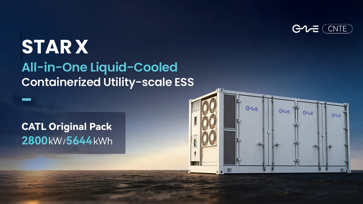
CNTE Launches STAR X Liquid-Cooled DC/AC Integrated Energy Storage System at Intersolar Europe 2026
Jul 06, 2026 -
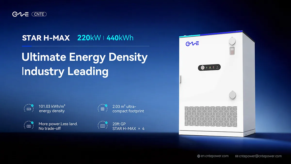
CNTE Unveils New STAR H-MAX Liquid-Cooled C&I ESS at Intersolar Europe 2026
Jun 23, 2026 -
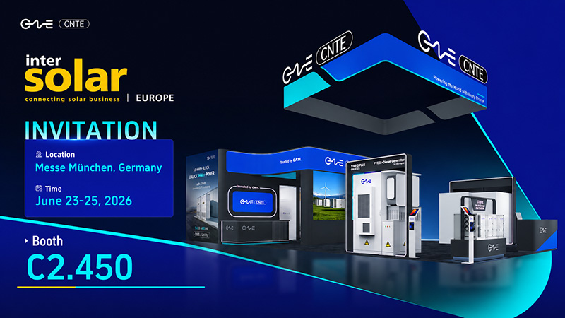
CNTE to Participate in Intersolar Europe 2026
May 20, 2026 -
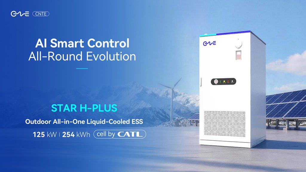
CNTE at KEY ENERGY 2026: Showcases STAR H-PLUS Outdoor Liquid-Cooled Energy Storage System
Mar 05, 2026 -

CNTE Honored as 2025 Forbes China Leading Global Brand
Jul 06, 2026 -
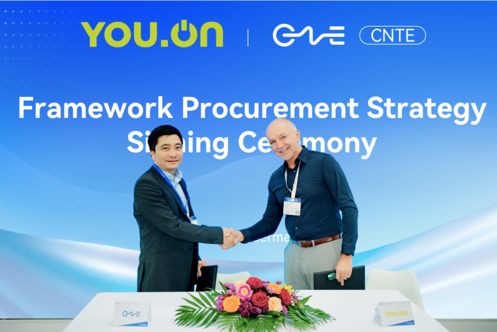
CNTE & YOU.ON Partner to Expand Storage Markets
May 19, 2025 -

CNTE Unveils Energy Storage Lineup at Solartech 2025
May 19, 2025 -
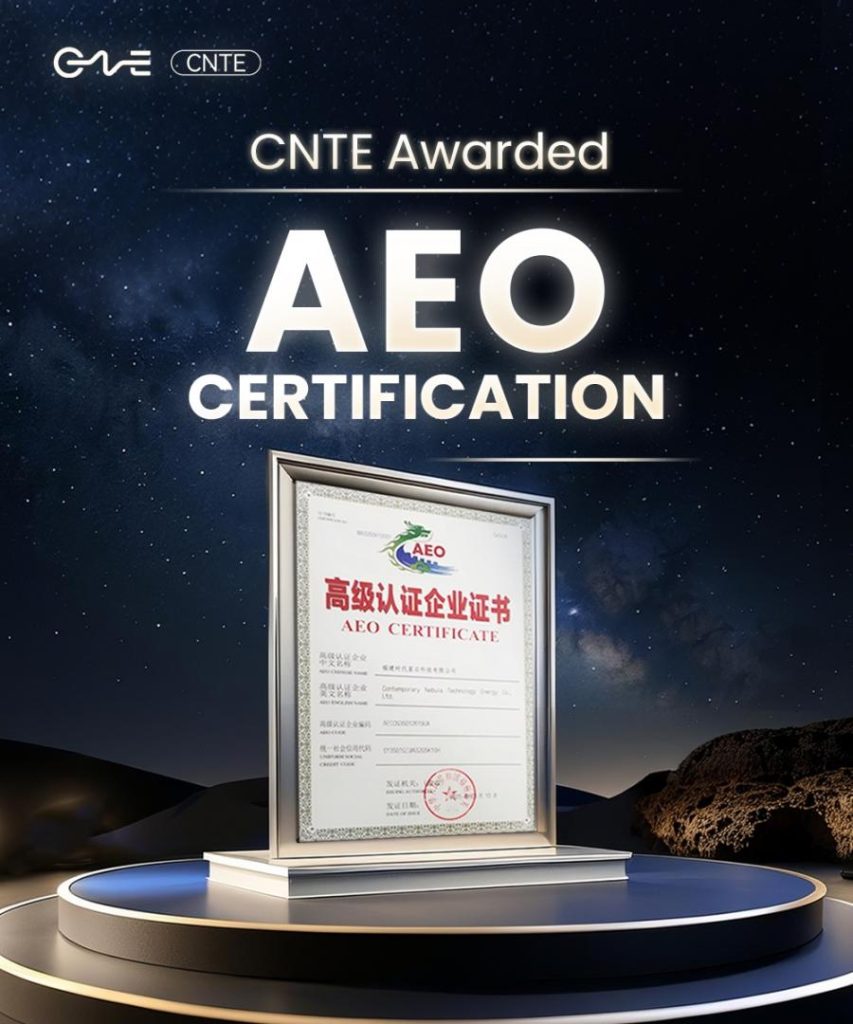
CNTE awarded AEO certification
Jul 06, 2026 -
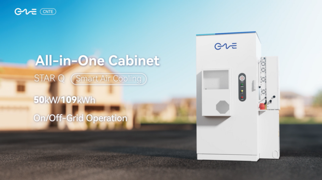
CNTE New Product Launch STAR Q
Jan 15, 2025 -
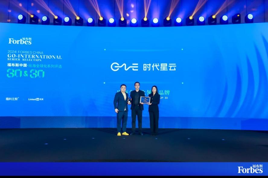
CNTE Named to Forbes China 2024 Top 30 Go-International Brands
Jul 06, 2026
