
High-Efficiency Lithium Battery Storage System Solutions for Grid Reliability
The global shift toward high-penetration renewable energy grids has transformed energy storage from a secondary balancing mechanism into a foundational infrastructure asset. Industrial facilities, commercial campuses, and transmission operators face unprecedented demands for power quality, intermittent generation smoothing, and fast-frequency regulation. Meeting these operational requirements demands a high-performance lithium battery storage system capable of continuous cycling under variable load profiles while maintaining strict thermodynamic and electrical boundaries.
Modern utility-scale and commercial installations require an exhaustive understanding of cell electrochemistry, power conversion dynamics, and digital asset governance. Evaluating these technologies requires looking past surface-level energy density metrics to examine the systemic integration parameters that define true levelized cost of storage, round-trip efficiency, and long-term asset availability.
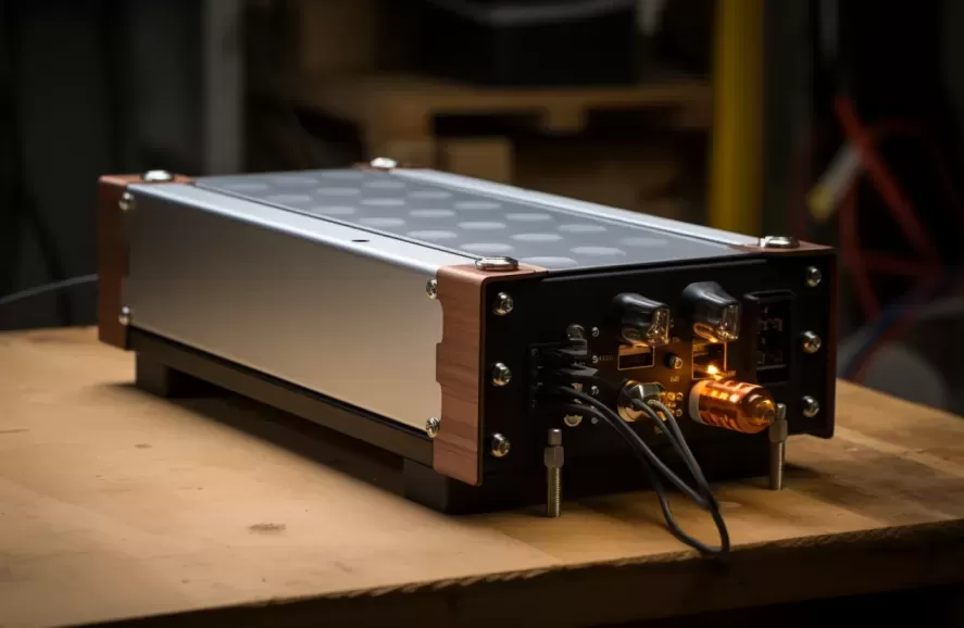
Cell Electrochemistry and Degradation Mechanisms
The operational lifespan and dispatch reliability of utility energy storage depend largely on the underlying electrochemical cell design. Lithium Iron Phosphate (LiFePO4 or LFP) has emerged as the global benchmark for stationary applications, displacing Nickel Manganese Cobalt (NMC) formulations across the majority of grid-tied deployments. The primary driver behind this shift lies in the intrinsic stability of the olivine crystal structure found in LFP cathodes. Under extreme electrical cycling or elevated operating temperatures, the P-O covalent bonds within the cathode prevent the exothermic oxygen release typical of layered transition metal oxides, effectively preventing thermal runaway propagation at the cell level.
Beyond baseline thermal stability, electrochemistry governs long-term degradation rates. System design must account for two distinct aging regimes: calendar aging and cyclic aging.
- Calendar Aging: Driven primarily by resting state of charge (SoC) and cell temperature. Extended operations at states above 80% SoC combined with ambient temperatures exceeding 35 degrees Celsius accelerate the growth of the Solid Electrolyte Interphase (SEI) layer on the graphite anode, consuming active lithium inventory.
- Cyclic Aging: Dictated by the Depth of Discharge (DoD), mechanical stress from lithium intercalation, and charging rates (C-rate). Full-depth cycles (0–100% SoC) induce micro-cracking within cathode particles, leading to impedance growth and capacity fade over consecutive operating cycles.
To counteract these degradation pathways, contemporary systems utilize engineered graphite anodes with silicon doping and optimized electrolytes containing film-forming additives. These modifications maintain electrochemical interfacial stability, allowing high-tier systems to deliver between 6,000 and 10,000 cycles at 80% DoD under controlled operating regimes.
Thermal Management Architecture: Liquid Cooling vs. Forced Air
System operational availability is inextricably tied to thermal uniformity across the energy storage enclosure. Uneven temperature distribution creates localized impedance mismatches among cells arranged in series and parallel strings. Cells operating at higher temperatures degrade faster, causing string-level capacity limitations where the weakest cell dictates the usable energy window of the entire rack.
While early containerized energy storage relied on centralized forced-air HVAC systems, modern multi-megawatt systems utilize closed-loop liquid cooling plates directly coupled to the base or sides of prismatic cells. Liquid cooling provides significantly higher heat transfer coefficients than air, allowing the cooling infrastructure to maintain cell-to-cell temperature deltas below 3 degrees Celsius across an entire 20-foot container.
By routing a dielectric fluid or a water-glycol mixture through micro-channel plates, liquid thermal management systems dramatically reduce parasitic auxiliary loads. Forced-air systems can consume up to 8% to 12% of total container energy throughput simply running high-volume air handlers, whereas modern liquid circuits reduce auxiliary consumption down to 2% to 4%. This efficiency delta directly enhances Round-Trip Efficiency (RTE), lifting real-world operational RTE from roughly 85% in older air-cooled designs to over 90% in advanced liquid-cooled solutions.
Multilevel BMS Design and Real-Time State Estimation
Monitoring thousands of individual cells distributed across high-voltage DC buses requires a hierarchical Battery Management System (BMS). The standard industrial architecture employs a three-tier topology:
- Tier 1: Cell Monitoring Units (CMU): Integrated directly into cell modules, monitoring individual cell voltages, terminal temperatures, and executing passive or active balancing commands.
- Tier 2: Rack Management Units (RMU): Aggregating telemetry from up to 24 CMUs, calculating string-level state parameters, controlling the string high-voltage breaker, and executing ground-fault detection.
- Tier 3: System Array Controller: Communicating across multiple RMUs, interfacing with the external Power Conversion System (PCS) and Energy Management System (EMS) via industrial Ethernet protocols such as Modbus TCP and IEC 61850.
Precise State of Charge (SoC), State of Health (SoH), and State of Power (SoP) estimation depends on sophisticated mathematical models running at the RMU and system controller levels. Simple Coulomb counting fails over extended operating periods due to sensor drift and current measurement errors. Modern systems combine Coulomb counting with Extended Kalman Filtering (EKF) and equivalent circuit modeling (ECM). This dual-layer algorithmic approach factors in internal resistance changes, polarization effects, and ambient temperature deviations to maintain SoC estimation accuracy within a plus-or-minus 1% margin across the full operating range.
Advanced system integrators such as CNTE (Contemporary Nebula Technology Energy Co., Ltd.) focus on tight integration between digital telemetry and hardware protection layers. By implementing sub-millisecond response thresholds and predictive fault diagnosis algorithms at the controller level, modern platforms isolate localized electrical anomalies long before they impact adjacent string architectures.
Integration with Power Conversion Systems (PCS) and Grid-Tied Controls
The DC battery array must interface with the medium-voltage AC grid through a bi-directional Power Conversion System. Modern installations are shifting from 1000V DC topologies to 1500V DC bus architectures. Stepping up to 1500V allows higher energy density per container, lowers current throughput for an equivalent power rating, reduces cable conductor cross-sections, and minimizes thermal I²R losses across the DC distribution network.
Modern PCS units utilize Silicon Carbide (SiC) or advanced Insulated Gate Bipolar Transistors (IGBTs) capable of four-quadrant operation, enabling independent active power (P) and reactive power (Q) control. System architectures are broadly bifurcated into centralized and string topologies:
- Centralized Inverter Topologies: Multiple DC strings are paralleled into a massive central inverter (1 MW to 3.45 MW). While offering lower initial capital cost per megawatt, centralized designs can suffer from circulating currents between strings of varying internal resistance and aggregate capacity loss if one string degrades prematurely.
- String Inverter Topologies: Each battery rack or small cluster of racks pairs with an independent, smaller PCS unit (100 kW to 250 kW). This decentralized approach eliminates inter-string mismatch losses, isolates maintenance events without disabling the whole block, and allows more precise local maximum power tracking at the cost of higher inverter unit count.
Grid integration also relies on advanced grid-forming control algorithms. While traditional grid-following storage requires an external voltage and frequency reference from the primary grid, grid-forming systems act as virtual synchronous machines. Using droop control and virtual inertia synthesis, a grid-forming lithium battery storage system can stabilize weak grids, manage high rates of change of frequency (RoCoF), and deliver black-start capabilities during blackouts.
Commercial and Industrial Deployment Models
In Commercial and Industrial (C&I) sectors, economic return on investment hinges on multi-application value stacking. Operating a single asset to perform only one function frequently extends the payback horizon beyond acceptable enterprise thresholds. Modern facilities program their energy control platforms to orchestrate several parallel operational modes:
Demand charge management represents the primary financial driver for energy-intensive industrial facilities. Commercial utility tariffs often calculate billing based on peak fifteen-minute power draw over a billing cycle. By dynamically discharging within milliseconds of a facility load surpassing a preset threshold, the system trims peak demand, yielding direct tariff savings without disrupting production schedules.
Solar-plus-storage integration eliminates the intermittency challenges inherent to on-site photovoltaic generation. Systems buffer midday solar overproduction, preventing zero-export curtailment dictated by local utilities. The stored low-cost energy is dispatched during peak evening pricing windows, optimizing time-of-use (ToU) arbitrage. Facilities facing grid reliability issues also utilize industrial storage to maintain seamless operation for critical loads, isolating production equipment from voltage sags, brownouts, and brief interruptions without the emissions or slow transfer times of diesel generation.
Technical Specification Comparison Matrix
Selecting equipment requires evaluating standard parameters across differing application profiles. The table below outlines standard industrial engineering metrics for modern installations:
| Technical Parameter | C&I Energy-Shift Profile | Utility Frequency Regulation Profile |
|---|---|---|
| Nominal Discharge Rate (C-Rate) | 0.5C (2-hour duration) | 1C to 2C (0.5 to 1-hour duration) |
| Target DC System Voltage | 1000V – 1500V DC | 1500V DC |
| Cooling Topology | Liquid-to-Air Plate Exchangers | Integrated Direct Liquid Chillers |
| Design Round-Trip Efficiency (AC-AC) | 87.5% – 90.0% | 85.0% – 88.5% |
| Enclosure Rating & Footprint | NEMA 3R / IP55 Modular Cabinet | ISO 20ft Standardized Container |
| Communication Interface | Modbus TCP, BACnet, Sunspec | IEC 61850, DNP3, Modbus TCP |
Selecting the correct profile balances physical footprint against thermal management headroom. High C-rate utility operations generate rapid internal heat requiring aggressive active chilling, while 0.5C industrial energy shifting prioritizes volumetric energy density and minimal parasitic pumping losses.
System Safety and International Compliance Standards
Engineering a modern energy storage asset requires satisfying a complex matrix of global safety standards. Rather than relying on singular fail-safes, compliant designs implement defense-in-depth methodologies across mechanical, electrical, and chemical domains.
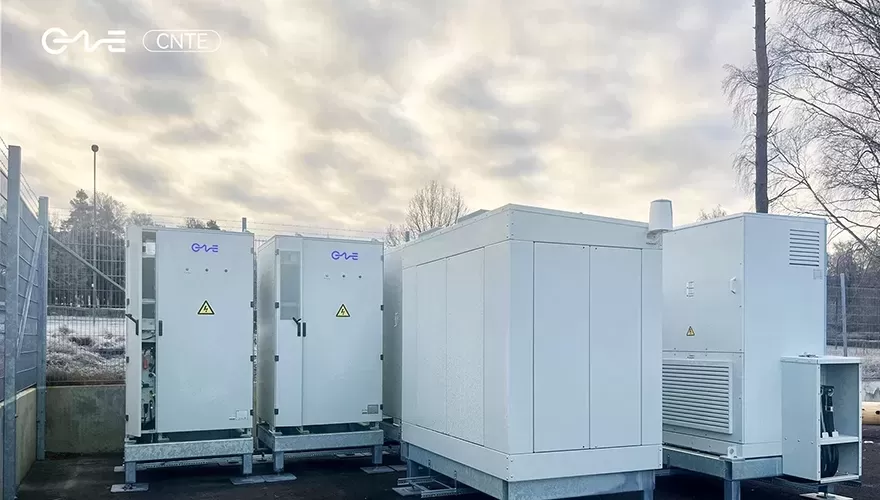
System integrators must build hardware that passes rigorous testing regimens, including UL 9540A, which assesses thermal runaway propagation at the cell, module, unit, and installation levels. Compliance with UL 9540 (Energy Storage Systems and Equipment) and UL 1973 (Batteries for Use in Stationary Applications) ensures physical containment, operational control safety, and high-voltage electrical safety under faulted conditions.
In addition to electrical standards such as IEC 62619 and NFPA 855 installation parameters, mechanical construction must incorporate deflagration venting systems designed in accordance with NFPA 68. Early-stage gas detection arrays—measuring trace parts per million of hydrogen (H2) and carbon monoxide (CO)—must trigger automated ventilation long before volatile gas concentrations reach lower flammability limits. Advanced manufacturing standards from CNTE (Contemporary Nebula Technology Energy Co., Ltd.) apply these multi-tier containment architectures, ensuring that utility and commercial battery systems integrate cleanly into dense municipal or commercial areas without compromising facility safety.
Frequently Asked Questions (FAQ)
What are the primary factors affecting the Levelized Cost of Storage (LCOS) in stationary batteries?
LCOS is primarily governed by initial capital expenditure (CAPEX), system round-trip efficiency (RTE), cycle life degradation curves, and ongoing operational/auxiliary maintenance costs (OPEX). A cheaper system with low round-trip efficiency or rapid cell capacity fade will incur a significantly higher lifetime LCOS than a high-efficiency system optimized for thousands of operational cycles.
How does liquid cooling outperform forced-air cooling in high-density battery enclosures?
Liquid cooling provides a heat transfer coefficient up to 25 times greater than air, maintaining cell-to-cell temperature variations under 3 degrees Celsius. This precise thermal regulation suppresses the accelerated aging of edge cells, mitigates string impedance imbalances, and lowers auxiliary power consumption by 50% or more compared to large HVAC fans, directly improving AC-to-AC system efficiency.
What is the functional difference between grid-following and grid-forming inverters?
Grid-following inverters track the local utility's existing voltage and frequency waveform using phase-locked loops (PLLs) to inject active or reactive current. Grid-forming inverters establish their own independent voltage and frequency references, operating as a virtual synchronous generator capable of microgrid operation, black-starting dead lines, and damping grid frequency oscillation.
Why is a 1500V DC system architecture preferred over 1000V DC for large installations?
Operating at 1500V DC reduces the electrical current required to transmit equivalent levels of power. Lower current directly translates to reduced resistive losses (I²R losses), permits smaller conductor sizes, simplifies combiner configurations, and enables larger multi-megawatt blocks tied to a single inverter platform, driving down balance-of-system hardware and installation expenses.
How does an Advanced Battery Management System (BMS) balance cells during operation?
Modern BMS units utilize active or passive balancing. Passive balancing uses resistive bleed circuits to dissipate excess charge as heat from the highest-voltage cells during the late stages of a charge cycle. Active balancing uses inductive or capacitive energy-transfer circuits to shuttle charge from higher-voltage cells to lower-voltage cells within the string, preserving usable energy and minimizing thermal generation.
Engineering Inquiries and System Specification Requests
Deploying a resilient, utility-grade lithium battery storage system demands rigorous technical coordination across electrical topologies, mechanical thermal controls, and enterprise software layers. System configurations must be custom-tailored to balance load dynamics, thermal parameters, interconnection regulations, and financial hurdles.
CNTE provides dedicated engineering consultations for complex industrial, commercial, and utility energy storage projects. Connect with our engineering and systems architecture team to request detailed technical datasheets, initiate full system sizing simulations, or review complete containerized electrical schematics tailored to your specific project requirements.
Get in Touch
Recent Posts
-
CNTE Included in BloombergNEF's Q4 2026 Tier 1 Energy Storage Manufacturers
Nov 03, 2026 -
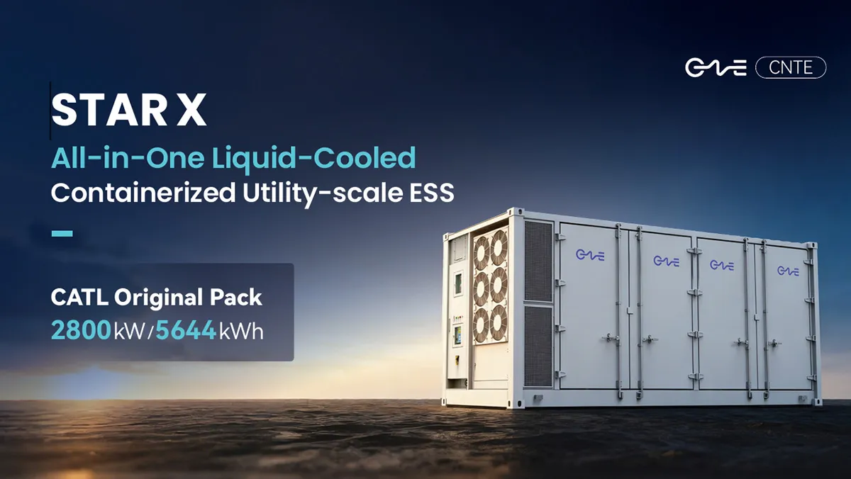
CNTE Launches STAR X Liquid-Cooled DC/AC Integrated Energy Storage System at Intersolar Europe 2026
Jul 06, 2026 -
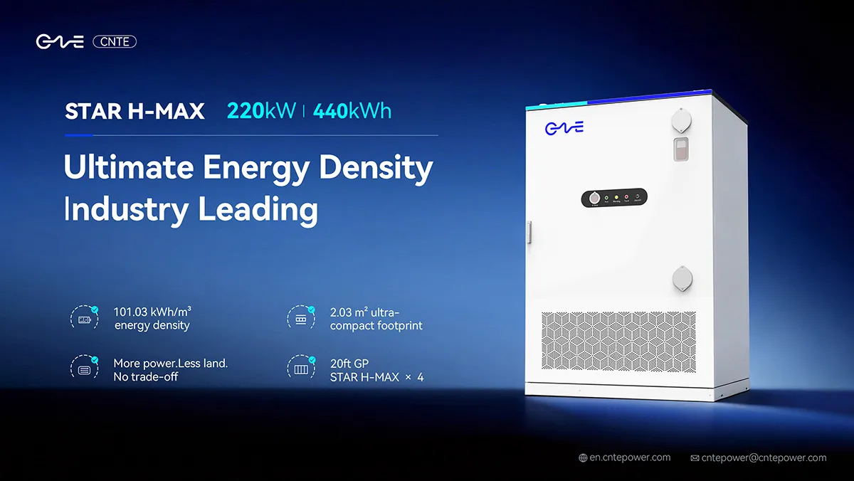
CNTE Unveils New STAR H-MAX Liquid-Cooled C&I ESS at Intersolar Europe 2026
Jun 23, 2026 -
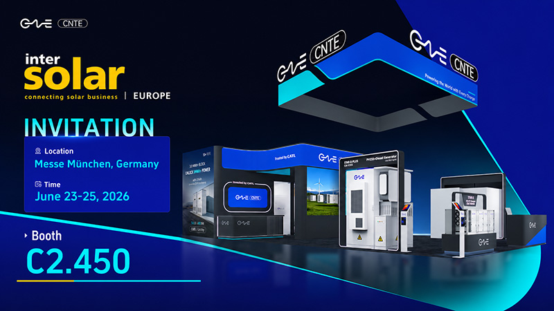
CNTE to Participate in Intersolar Europe 2026
May 20, 2026 -
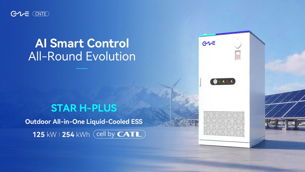
CNTE at KEY ENERGY 2026: Showcases STAR H-PLUS Outdoor Liquid-Cooled Energy Storage System
Mar 05, 2026 -

CNTE Honored as 2025 Forbes China Leading Global Brand
Jul 06, 2026 -

CNTE & YOU.ON Partner to Expand Storage Markets
May 19, 2025 -

CNTE Unveils Energy Storage Lineup at Solartech 2025
May 19, 2025 -
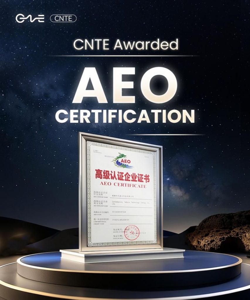
CNTE awarded AEO certification
Jul 06, 2026 -
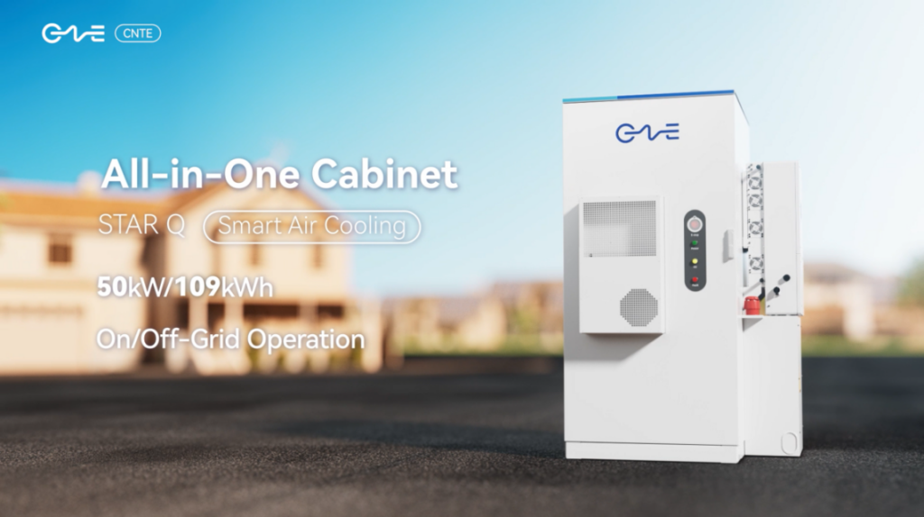
CNTE New Product Launch STAR Q
Jan 15, 2025
