5 Engineering Standards for Deploying High Capacity Energy Storage in Commercial Settings
The modernization of utility grids and heavy industrial operations demands a fundamental shift in energy management. With intermittent renewable generation from solar and wind assets expanding globally, conventional power distribution infrastructures face structural imbalances. These imbalances manifest as voltage fluctuations, frequency deviations, and peak demand spikes that traditional thermal power plants struggle to mitigate efficiently. To address these systemic mismatches, high capacity energy storage has transitioned from an experimental asset class into an indispensable foundation of modern power grids.
As industrial operators and utility planners aim to decarbonize operations while maintaining uptime, selecting the appropriate storage architecture is a paramount decision. Contemporary Nebula Technology Energy Co., Ltd. (CNTE) provides advanced engineering solutions designed to meet these high-power demands. Understanding the electrochemical, thermal, and economic dimensions of these systems is a prerequisite for successful deployment.
Electrochemical Foundations and Structural Architecture
The performance of any high capacity energy storage installation depends on its core electrochemical cell chemistry and how those cells are organized into modules, racks, and containers. While multiple chemistries exist, Lithium Iron Phosphate (LFP) has emerged as the industry standard for stationary applications due to its chemical stability, long cycle life, and thermal characteristics.
To construct a system capable of delivering multi-megawatt output over extended periods, individual cells are arranged through a hierarchy of electrical connections:
Cell Level: Prismatic LFP cells, typically rated at 3.2V with capacities exceeding 280Ah or 306Ah, serve as the building blocks.
Module Level: Cells are connected in series and parallel to increase voltage and capacity, integrated with localized voltage and temperature sensors.
Rack Level: Multiple modules are stacked vertically in a structural enclosure, incorporating a localized circuit breaker, a switchgear assembly, and a slave Battery Management System (BMS).
Container Level: Racks are aligned within standardized ISO containers (often 20-foot or 40-foot configurations), complete with centralized power conversion systems, HVAC or liquid cooling loops, and active fire suppression systems.
Engineering designs engineered by CNTE utilize high-density LFP configurations that maximize volumetric efficiency. This allows operators to achieve greater megawatt-hour (MWh) capacity per square meter of land, reducing civil engineering expenses and footprint requirements at the installation site.
The Multi-Tiered Battery Management System
Managing a massive network of electrochemical cells requires a highly responsive control architecture. A three-tiered Battery Management System (BMS) is deployed to maintain operational equilibrium and prevent cell degradation:
The first tier consists of the Module BMS, which monitors individual cell voltages and temperatures. Passive or active cell balancing is executed at this level to prevent single cells from reaching over-charge or over-discharge thresholds, which would limit the usable capacity of the entire string.
The second tier is the Rack BMS, which aggregates data from the module controllers, calculates the overall State of Charge (SoC) and State of Health (SoH), and manages the rack-level contactors. This tier coordinates safety isolation if operational parameters deviate from nominal values.
The third tier is the System BMS or Master Controller. This unit interfaces directly with the Power Conversion System (PCS) and the facility-wide Energy Management System (EMS). It translates external dispatch signals—such as frequency regulation commands or peak-shaving schedules—into localized charge and discharge profiles across all active racks.
Thermal Management and Enclosure Safety Engineering
Thermal stability is a primary focus when deploying high capacity energy storage systems in demanding environments. The continuous charging and discharging of dense battery banks generate resistive heat, which, if unmanaged, accelerates capacity fade and compromises system safety.
Traditional forced-air cooling designs are increasingly replaced by liquid cooling loops. Liquid cooling provides a significantly higher heat transfer coefficient than air, allowing for precise temperature control across the entire battery volume. By routing coolant channels directly adjacent to the battery cells, the temperature variance between cells can be maintained within a narrow window (typically less than 3 degrees Celsius). This uniform temperature distribution prevents localized hot spots, ensuring uniform cell degradation and extending the overall operational lifespan of the asset.
CNTE integrates liquid-cooled plates within its standard containerized storage products. This design mitigates the parasitic power consumption associated with heavy HVAC fan operation, leading to improved round-trip efficiency (RTE) for the entire facility. Additionally, these systems incorporate multi-stage safety containment measures:
Off-Gas Detection: Specialized sensors monitor for trace concentrations of carbon monoxide and hydrogen, indicating early-stage cell venting long before thermal anomalies are detected by standard temperature sensors.
Deflagration Mitigation: Pressure relief panels built into the container roof release internal pressure in the event of rapid gas accumulation, preserving structural integrity.
Active Fire Suppression: Clean agent gas suppression systems (such as Novec 1230 or FM-200) are paired with localized water deluge backups to suppress thermal events quickly and protect surrounding assets.
Primary Applications in Commercial and Industrial Sectors
Industrial facilities and utility operators deploy high capacity energy storage to resolve distinct operational and financial challenges. These applications require specific performance profiles from the storage system, ranging from rapid millisecond power bursts to sustained multi-hour energy delivery.
Industrial Demand Charge Mitigation
Many commercial and industrial electrical tariffs include substantial demand charges based on the peak power consumed during a single billing period. By utilizing peak-shaving algorithms, the storage system discharges during these high-demand periods, keeping grid consumption below a predetermined threshold. This reduces monthly operational expenses without requiring alterations to industrial production schedules.
Integration with Large-Scale Renewable Generation
Utility-scale solar and wind farms face curtailment mandates when local generation exceeds transmission capacity. Integrating high capacity energy storage allows developers to capture excess green energy during peak production hours and dispatch it to the grid when demand—and market pricing—is higher. This process, known as energy arbitrage, stabilizes the local grid and improves the financial yield of the renewable facility.
Microgrids and Back-up Power Infrastructure
For remote industrial sites, such as mining operations or deepwater ports, maintaining a continuous power supply is essential. When configured as part of a microgrid, a high capacity energy storage system can operate in grid-forming mode, establishing voltage and frequency references for the entire facility. In the event of an upstream grid failure, the system transitions the facility to islanded operation within milliseconds, preventing costly production downtime.
Financial Valuation and Levelized Cost of Storage
Evaluating the feasibility of a large-scale energy storage project requires looking beyond initial capital expenditure (CAPEX) to analyze the Levelized Cost of Storage (LCOS). This metric accounts for all lifetime costs divided by the total energy delivered over the operational life of the system.
Several variables exert direct control over the LCOS of a high capacity energy storage installation:
Round-Trip Efficiency (RTE): The ratio of energy retrieved from the storage system to the energy put into it. Higher RTE decreases the amount of energy lost during operations, improving long-term project economics.
Depth of Discharge (DoD): Operating a system at a higher DoD provides more usable capacity but can accelerate capacity degradation if the battery chemistry is not engineered to withstand deep cycling.
Calendar and Cycle Life: High-quality LFP cells are expected to maintain at least 80% of their original capacity after 6,000 to 10,000 full charge-discharge cycles, depending on operating temperatures and C-rates.
Maintenance and Operations (OPEX): Routine HVAC servicing, coolant replacement, and electrical calibrations must be structured to minimize system downtime.
To optimize these variables, CNTE focuses on delivering integrated systems where the power electronics, battery chemistry, and thermal management loops are designed to work together. This unified approach reduces compatibility issues during commissioning and lowers ongoing OPEX, helping project developers secure favorable financing terms and realize a rapid return on investment.
Frequently Asked Questions
Q1: What defines a system as a high capacity energy storage installation?
A1: High capacity energy storage systems are typically characterized by their ability to store and dispatch energy at the megawatt (MW) or megawatt-hour (MWh) scale. These installations are engineered for utility substation integration, large industrial manufacturing plants, data centers, and grid-scale renewable generation facilities, distinguishing them from smaller residential or light commercial battery units.
Q2: Why is Lithium Iron Phosphate (LFP) preferred over Nickel Manganese Cobalt (NMC) for large-scale applications?
A2: LFP is preferred in high capacity energy storage installations due to its superior chemical stability, which significantly reduces the likelihood of thermal runaway. Furthermore, LFP chemistry delivers a much longer cycle life—often exceeding 8,000 cycles at 80% Depth of Discharge—compared to NMC, resulting in a lower Levelized Cost of Storage over the lifetime of a long-term project.
Q3: How does liquid cooling compare to air cooling in terms of system longevity?
A3: Liquid cooling offers superior thermal conductivity compared to air cooling, keeping internal cell temperatures highly uniform. By keeping the temperature variance between cells within a tight range of 2 to 3 degrees Celsius, liquid cooling prevents localized thermal stress. This uniform environment minimizes cell degradation rates across the entire battery container, extending the asset life by up to 20% compared to traditional forced-air designs.
Q4: Can a high capacity energy storage system operate in sub-zero environments?
A4: Yes, modern systems are engineered with internal heating systems integrated into the liquid cooling loop. When environmental temperatures fall below freezing, the system uses localized thermal management to warm the battery modules to an optimal operational temperature before charging begins, preventing lithium plating and maintaining cell capacity.
Q5: What is the typical physical footprint required for a 10MWh containerized storage system?
A5: A standard 10MWh high capacity energy storage system can typically be housed in two or three 20-foot ISO containers, depending on the energy density of the cells and the integration of the power conversion equipment. Including clearances for cooling systems, maintenance access, and fire safety corridors, the physical footprint is highly compact, making it suitable for space-constrained industrial environments.
Consultation and Engineering Support
Selecting and deploying a high capacity energy storage solution is a complex process that requires deep alignment between chemical, electrical, and structural engineering disciplines. Every facility presents unique load profiles, environmental conditions, and interconnection requirements that must be carefully analyzed during the design phase.
CNTE provides comprehensive system design, engineering, and manufacturing services to assist you at every stage of project development. Our engineering teams work closely with utility operators, EPC contractors, and industrial facility managers to configure tailored, liquid-cooled energy storage systems that maximize uptime and control operational costs.
To discuss your project specifications, obtain system datasheets, or receive a preliminary engineering analysis for your site, please submit a formal inquiry to our application engineering department.
Get in Touch
Recent Posts
-
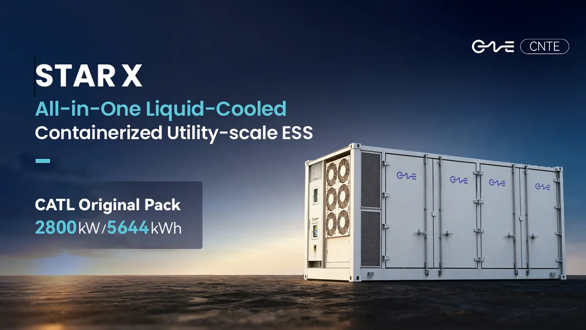
CNTE Launches STAR X Liquid-Cooled DC/AC Integrated Energy Storage System at Intersolar Europe 2026
Jul 06, 2026 -
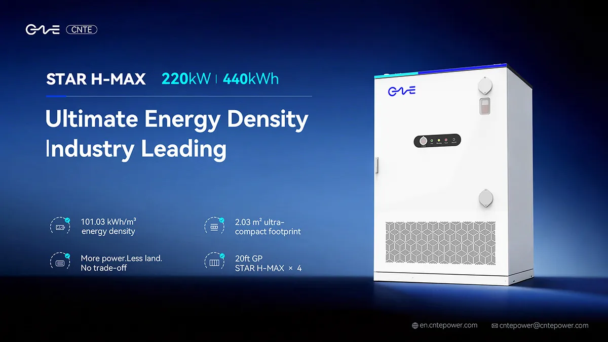
CNTE Unveils New STAR H-MAX Liquid-Cooled C&I ESS at Intersolar Europe 2026
Jun 23, 2026 -
CNTE to Participate in Intersolar Europe 2026
May 20, 2026 -
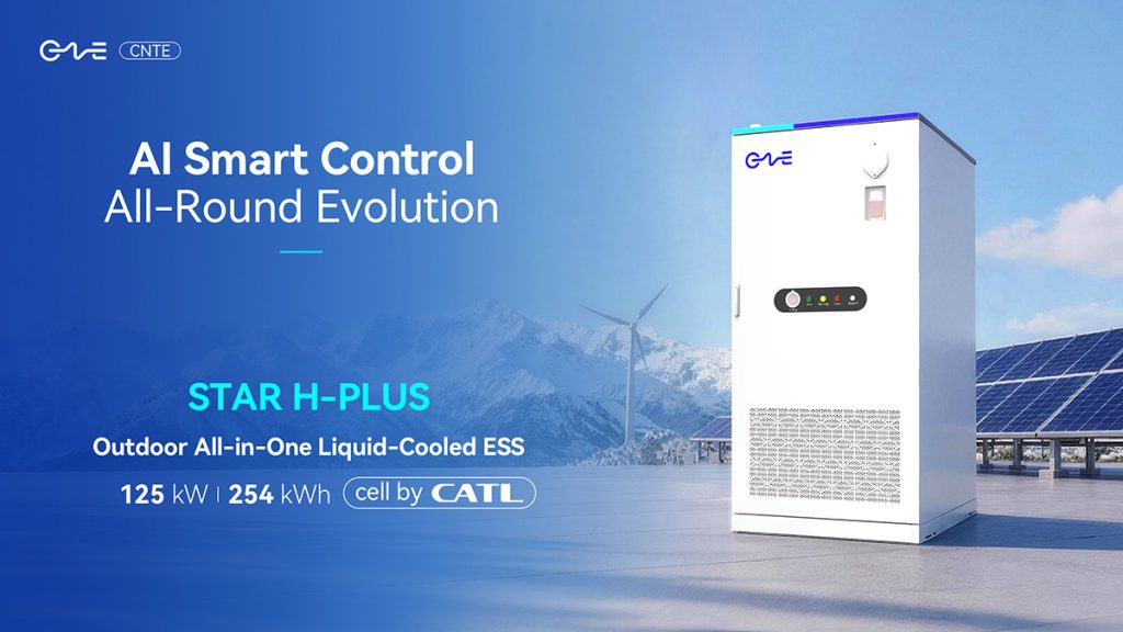
CNTE at KEY ENERGY 2026: Showcases STAR H-PLUS Outdoor Liquid-Cooled Energy Storage System
Mar 05, 2026 -
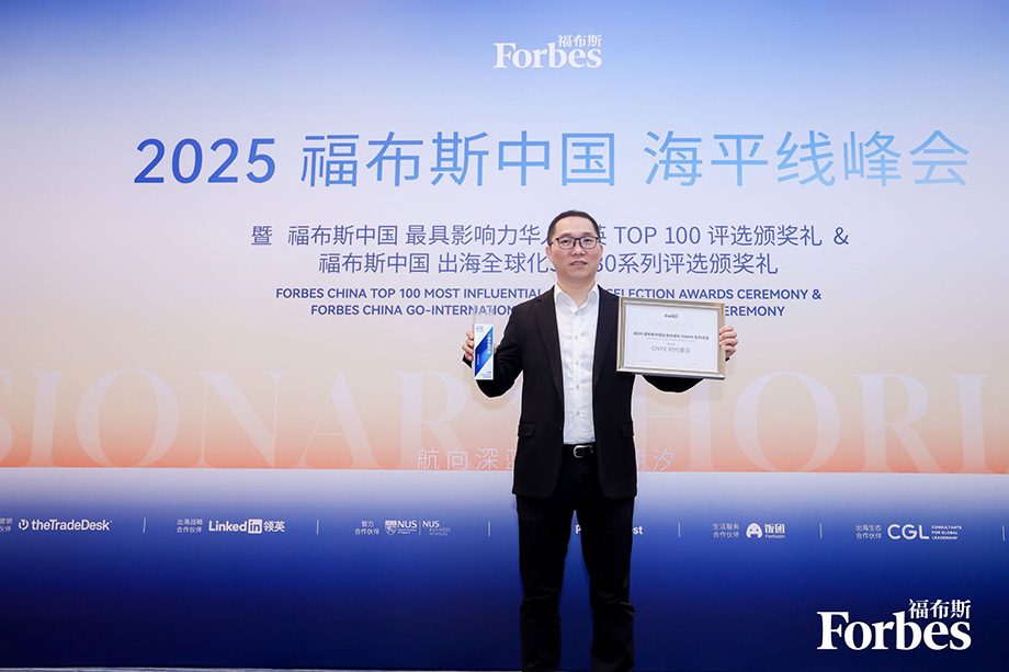
CNTE Honored as 2025 Forbes China Leading Global Brand
Jul 06, 2026 -
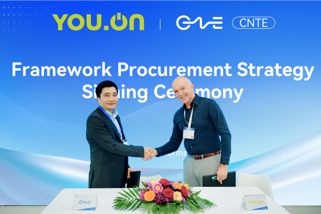
CNTE & YOU.ON Partner to Expand Storage Markets
May 19, 2025 -
CNTE Unveils Energy Storage Lineup at Solartech 2025
May 19, 2025 -
CNTE awarded AEO certification
Jul 06, 2026 -
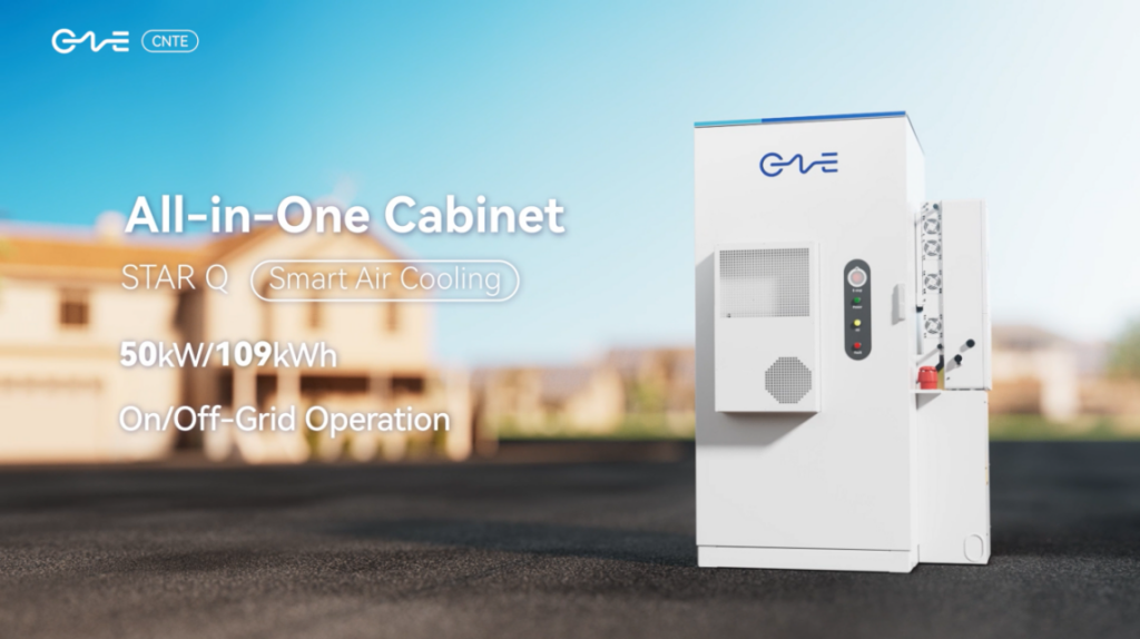
CNTE New Product Launch STAR Q
Jan 15, 2025 -
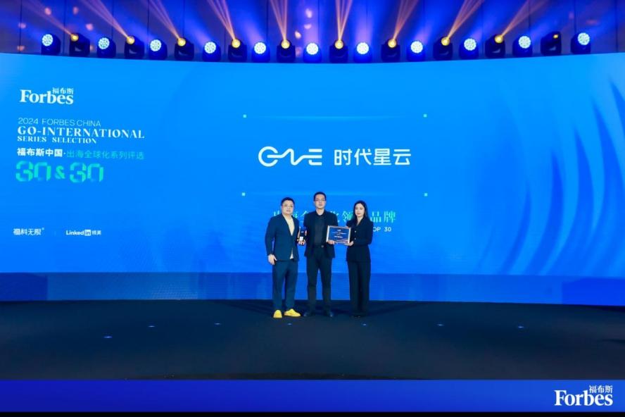
CNTE Named to Forbes China 2024 Top 30 Go-International Brands
Jul 06, 2026