
Photovoltaic Storage Integration: Engineering Guide for Utility & C&I Systems
The transformation of global energy networks requires clean generation assets to perform as predictable, dispatchable infrastructure. Intermittent solar irradiance presents substantial integration challenges to regional transmission and distribution grids, including frequency instabilities, voltage fluctuations, and curtailment issues during peak production windows. Deploying commercial and utility-scale photovoltaic storage bridges the operational gap between generation profiles and consumption demands, enabling dynamic capacity firming, black start capabilities, and synthetic inertia across distributed and centralized networks.
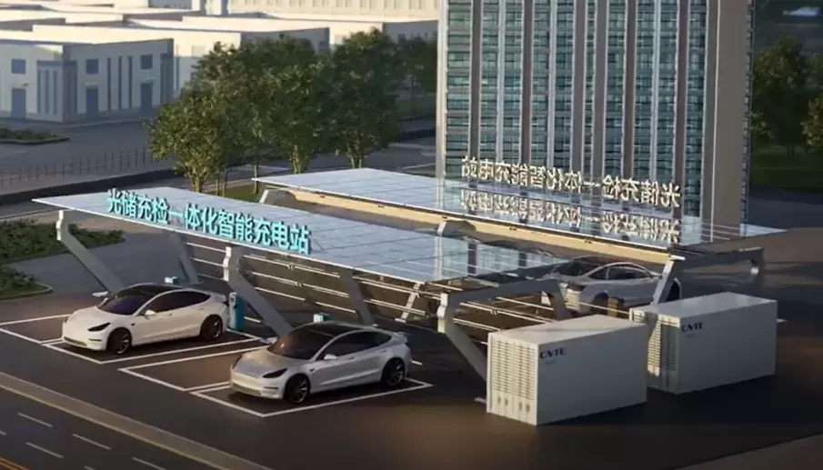
Topological Analysis: DC-Coupled vs. AC-Coupled System Architectures
Selecting the optimal power topology represents the foundational engineering decision in utility-scale and commercial energy projects. System designers evaluate capital expenditure against operational flexibility when sizing balance-of-plant (BOP) infrastructure.
DC-Coupled Architecture
In DC-coupled configurations, the photovoltaic array and the electrochemical Energian varastointi system (BESS) share a unified direct-current bus prior to power inversion. Both subsystems route through a shared bi-directional power conversion system (PCS) or central inverter before interconnecting with the medium-voltage step-up transformer.
Higher round-trip efficiency (RTE) for energy directed immediately from the PV modules into the battery racks, as the power bypasses DC-AC and AC-DC conversion stages.
Reduced balance-of-plant footprint, leveraging shared inverter hardware, consolidated medium-voltage switchgear, and fewer high-voltage transformer connections.
Capture of otherwise clipped solar energy during midday peak generation, routing excess capacity directly into storage without exceeding inverter thermal thresholds.
Increased engineering complexity within the DC string combiner boxes and multi-string maximum power point tracking (MPPT) inputs.
AC-Coupled Architecture
AC-coupled designs decouple the solar array from the Akku storage subsystem entirely on the DC side. The solar strings feed independent solar inverters, while the battery racks interface with dedicated bi-directional PCS units, synchronizing over a common alternating-current bus.
Independent operation of power blocks, allowing solar generation and battery charging or discharging to be metered, controlled, and maintained separately.
Direct integration advantages for retrofit projects, where existing photovoltaic installations require Energian varastointi without retrofitting established inverter infrastructure.
Simplified fault isolation, preventing DC-bus ground faults on the solar array from propagating to battery pack management systems.
Slightly lower composite round-trip efficiency due to secondary conversion steps during midday charging routines.
Subsystem Integration: Battery Chemistry, Multi-Tier BMS, and Inverter Topologies
A resilient storage system requires synchronized interaction between electrochemistry, supervisory electronics, and power semiconductors. System failures rarely stem from single component faults; they emerge from poor communication and control latency across subsystem interfaces.
Lithium iron phosphate (LFP) remains the prevailing electrochemical standard across commercial and utility installations. LFP offers thermal runaway thresholds above 270 degrees Celsius, high cycle life capabilities under elevated ambient temperatures, and zero cobalt dependencies. Advanced system configurations evaluate cell-level degradation characteristics against cyclic depth-of-discharge (DoD), typically optimizing operation between 10% and 90% State of Charge (SoC) to preserve active lithium inventory.
Hierarchical Battery Management Systems (BMS) govern operational safety and functional longevity across three primary tiers:
Level 1 (Cell/Module): Monitored by slave controllers executing voltage sensing down to single millivolt accuracy, accompanied by multi-point NTC thermistor surface monitoring. Passive or active cell balancing prevents state-of-charge drift across series-connected cell groups.
Level 2 (Rack/String): The master rack controller aggregates module telemetry, manages string-level contactors, calculates dynamic State of Health (SoH), and interfaces with DC high-speed circuit breakers.
Level 3 (System/Array Controller): Coordinates multi-rack configurations, interfaces with fire mitigation protocols, and exchanges telemetry with the external Power Conversion System via Modbus TCP/IP, CAN bus, or EtherCAT protocols with latency metrics below 20 milliseconds.
PCS architectures demand four-quadrant operation capable of providing active power control along with reactive power absorption or injection (VAR support). Modern deployments integrate grid-forming inverters equipped with virtual synchronous generator (VSG) algorithms. These systems establish an independent voltage and frequency reference, delivering instantaneous synthetic inertia to stabilize weak grids with low short-circuit ratios.
Lämpö Engineering and Mitigating Runaway Risks in Photovoltaic Storage Systems
Electrochemical reliability depends on maintaining uniform internal Käyttölämpötilas across all cells in a pack. Non-uniform thermal gradients accelerate uneven cell degradation, induce localized impedance mismatches, and raise systemic failure risks.
Traditional forced-air cooling systems struggle to manage the localized heat flux generated by continuous charge-discharge regimes above 0.5C. Liquid cooling topologies have emerged as the industry baseline for high-density containers. Using an ethylene glycol-water mixture routed through micro-channel cold plates positioned directly against cell casings, liquid systems maintain cell-to-cell thermal variations within 3 degrees Celsius. This narrow thermal band prevents premature capacity loss, minimizes parasitic cooling consumption, and reduces acoustic emissions across sensitive fence lines.
Turvallisuus frameworks demand multi-layered mechanical and electronic hazard mitigations:
Off-gas detection: Implementing early-stage hydrogen and carbon monoxide sensors capable of detecting initial electrolyte breakdown minutes before thermal excursion occurs.
Active venting systems: Pressure-relief ports paired with mechanical deflagration panels direct unexpected overpressures upward away from adjacent containers.
Zoned fire extinguishing: Aerosol or localized clean-agent suppression systems paired with high-volume deluge water manifolds for structural cooling and containment.
Lämpö barriers: Aerogel insulation sheets installed between individual cells to physically arrest heat propagation across neighboring units.
Multi-Scenario Deployment Archetypes
Industrial applications encounter disparate site conditions, duty cycles, and economic drivers. Structuring an effective system requires matching the power-to-energy ratio (C-rate) to the operational envelope of the project.
Commercial and Industrial (C&I) Behind-the-Meter (BTM)
Industrial manufacturing facilities, data hubs, and processing plants utilize storage systems primarily for peak shaving and load shifting. Operations operating under time-of-use (TOU) tariff structures charge battery units during low-rate morning intervals or directly from rooftop solar, discharging during peak afternoon demand windows. Integrated systems mitigate high capacity charges triggered by industrial motor starting currents, providing short-duration power backup to critical continuous-process loads.
Microgrids and Off-Grid Electrification
Remote mining operations, agricultural developments, and island networks integrate solar arrays with battery Energian varastointi and diesel generation assets. The energy management system controls dynamic droop curves, prioritizing renewable dispatch while maintaining a minimum spinning reserve on thermal generators. Advanced systems enable complete diesel-off operating modes under sufficient irradiance, driving fuel consumption and transport expenditures down dramatically.
Front-of-the-Meter (FTM) Utility-Scale Capacity
Centralized renewable generation facilities incorporate long-duration storage (typically 2-hour to 4-hour configurations) to support transmission and distribution utilities. These installations support capacity firming to fulfill power purchase agreements (PPA), provide primary frequency response within milliseconds of grid disturbances, and arbitrate day-ahead wholesale electricity pricing spreads.
For custom engineering and system integration across these complex environments, technical integration partners such as CNTE (Contemporary Nebula Technology Energy Co., Ltd.) provide specialized containerized architectures, ensuring structural, electrical, and control alignment across varied climate and operating profiles.
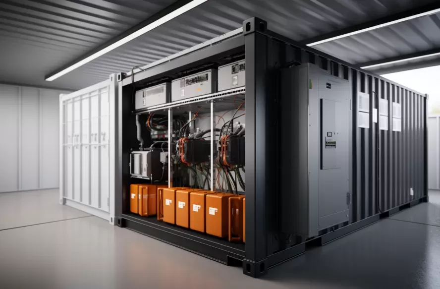
Procurement Specifications and Long-Term Degradation Economics
Evaluating multi-megawatt energy storage assets requires granular balance-sheet analysis moving beyond upfront capital expenditures per kilowatt-hour. Procurement managers and engineering teams calculate the Levelized Cost of Storage (LCOS) across the projected asset lifespan, which typically spans 10 to 20 years.
LCOS analysis models several interconnected mechanical and financial variables:
Capital Expenditure (CapEx): Core battery enclosures, PCS systems, switchgear, SCADA controls, engineering civil works, and utility interconnection assets.
Operational Expenditure (OpEx): Scheduled inspections, coolant flushes, air filter replacements, auxiliary power consumption (parasitic loads), and software maintenance.
Round-Trip Efficiency (RTE): System-level conversion performance accounting for DC resistance losses, inverter conversion efficiency, step-up transformers, and cooling power overhead.
Cyclic and Calendar Aging: Electrochemical degradation modeling based on average Käyttölämpötila, continuous DoD, and C-rate dynamics.
Augmentation Strategy: Planned mid-life capital deployment to install additional capacity blocks, offsetting natural capacity degradation without overbuilding initial storage banks.
Engineers evaluate whether a single-stage overbuild or a phased augmentation profile produces higher internal rates of return (IRR). Initial overbuilding increases Day 1 capital requirements and land footprint but minimizes ongoing site works. Phased augmentation relies on anticipated battery cost reductions and preserves cash flow, yet necessitates careful electrical design to prevent cross-charging and circulating currents between new, low-impedance strings and aged, high-impedance packs.
Asennus Protocols, Commissioning, and Control Integration
Transitioning from system delivery to commercial operation requires rigorous field verification routines. Quality issues left unaddressed during mechanical integration manifest as recurring communication drops, nuisance breaker trips, and localized overtemperature events during operations.
Civil foundations must support concentrated loads, as liquid-cooled battery containers frequently exceed 30 metric tons. Proper drainage paths, seismic anchor sizing, and blast mitigation distances between containers must comply strictly with local zoning and fire safety standards. Cable pathways require strict segregation between medium-voltage AC circuits, high-voltage DC string cables, and low-voltage telemetry lines to mitigate electromagnetic interference (EMI).
The site commissioning framework requires methodical execution:
Pre-Energization Cold Commissioning: Verifying insulation resistance (Megger testing), loop-checking dry contacts, confirming torque marks on all bolted copper busbar connections, and executing hydrostatic pressure testing on coolant circuits.
Hot Commissioning: Step-by-step energization of auxiliary systems, verification of internal container ventilation, calibration of gas detection arrays, and initialization of the multi-tier BMS.
Dynamic Inverter Tuning: Injecting reactive and active power commands to validate inverter response curves, testing islanding detection, and confirming automatic disconnection timing under simulated fault conditions.
SCADA and EMS Integration: Mapping telemetry registers into the site Energy Management System (EMS). System logic must process external grid signals, evaluate state-of-charge limits, and dispatch battery assets reliably. Supported directly through CNTE field engineering teams, these control platforms integrate deterministic control routines that prevent over-stressing critical power components.
System operators rely on SCADA systems running protocols such as DNP3, IEC 61850, or Modbus over optical fiber rings. Cloud-based condition monitoring platforms now apply machine-learning algorithms to historic telemetry, assessing cell impedance shifts and thermal deviations to identify anomalous degradation patterns before catastrophic electrical failure can occur.
Frequently Asked Questions
Q1: What is the standard operational lifespan of industrial LFP battery racks in commercial photovoltaic storage systems?
A1: Quality lithium iron phosphate cells operated under controlled thermal conditions (15 to 25 degrees Celsius) with a 0.5C charge/discharge profile generally achieve 6,000 to 8,000 equivalent full cycles before reaching their operational End-of-Life (EoL) threshold, defined as 70% or 80% retained capacity. In standard daily single-cycle applications, this correlates to an asset operational life of 15 to 20 years, provided systematic maintenance and cooling system servicing are sustained.
Q2: How does ambient temperature influence auxiliary power consumption and overall round-trip efficiency?
A2: Extreme ambient temperatures force active thermal management systems to run continuously. Under high ambient conditions (exceeding 40 degrees Celsius), liquid chillers must consume high parasitic power loads to extract thermal energy from the battery blocks. This auxiliary load draws power directly from the system, reducing net round-trip efficiency by 2% to 6% compared to operation under moderate ambient conditions.
Q3: What engineering methods prevent circulating currents when connecting multiple battery strings in parallel?
A3: Parallel string installations risk circulating currents if internal string voltages deviate during switching events. Engineering mitigations include integrating DC-DC converters on each string to decouple voltages, deploying automated string balancing routines that only close contactors when delta-voltage falls within strict tolerances (typically less than 5 to 10 volts), and ensuring symmetric DC cabling layouts to balance impedance throughout the busbar distribution network.
Q4: Why are grid-forming inverters preferred over grid-following inverters in high-penetration renewable sites?
A4: Grid-following inverters require an existing external AC voltage waveform provided by an operational transmission grid or synchronous generator to align their current injection. If the grid disconnects or destabilizes, grid-following units trip off. Grid-forming inverters establish their own stable voltage and frequency parameters through advanced software controls, acting as virtual voltage sources that can restart dark grids, support islanded microgrids, and enhance system stability across weak interconnection points.
Q5: What are the essential international safety standards governing the design and deployment of containerized storage?
A5: System design and certification evaluate three layers of criteria: cell and module safety (IEC 62619, UL 1642), complete system enclosure and functional safety (UL 9540, IEC 62933), and large-scale fire propagation mitigation (UL 9540A testing protocols). Electrical equipment, PCS units, and switchgear must also adhere to standard grid interconnection specifications such as IEEE 1547 and local utility compliance frameworks.
Engineered Solutions for Complex Power Demands
Modern renewable energy demands systems engineered for dynamic dispatch, long-term electrochemical resilience, and transparent field integration. CNTE provides advanced technical architecture, customized hardware designs, and integrated Akku storage technologies suited for demanding commercial, industrial, and utility infrastructure worldwide. Discuss your upcoming project requirements, technical specifications, and system integration strategies with our specialized engineering personnel at cntepower@cntepower.com.
Ota yhteyttä
Viimeisimmät julkaisut
-
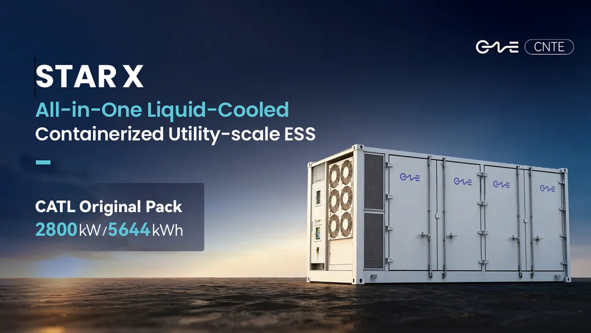
CNTE lanseeraa STAR X nestemäisesti jäähdytetyn DC/AC integroidun energian varastointijärjestelmän Intersolar Europe 2026 -tapahtumassa
Jul 06, 2026 -
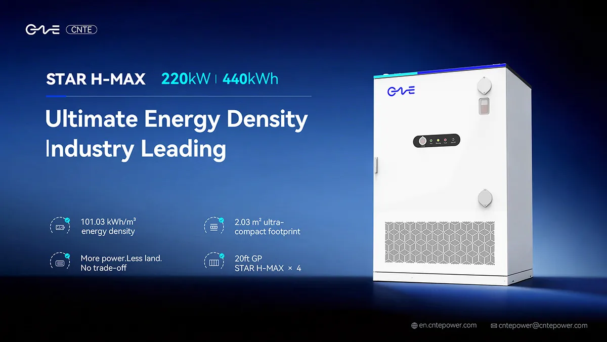
CNTE esittelee uuden STAR H-MAX nestemäisesti jäähdytetyn C&I ESS:n Intersolar Europe 2026 -messuilla
Jun 23, 2026 -
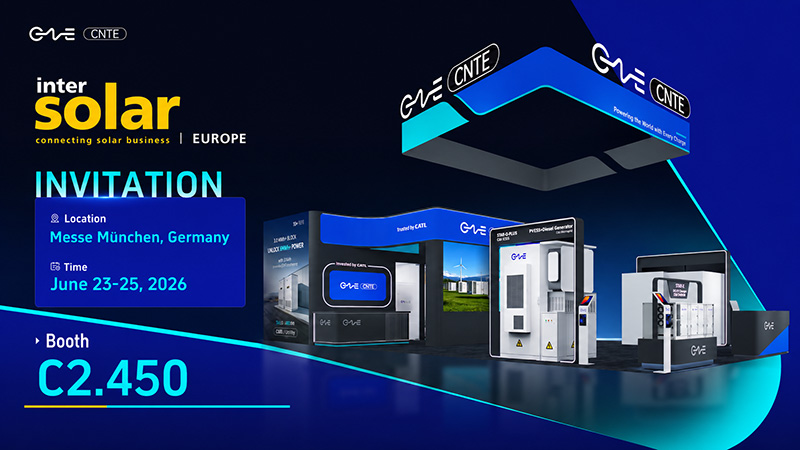
CNTE osallistuu Intersolar Europe 2026 -tapahtumaan
May 20, 2026 -
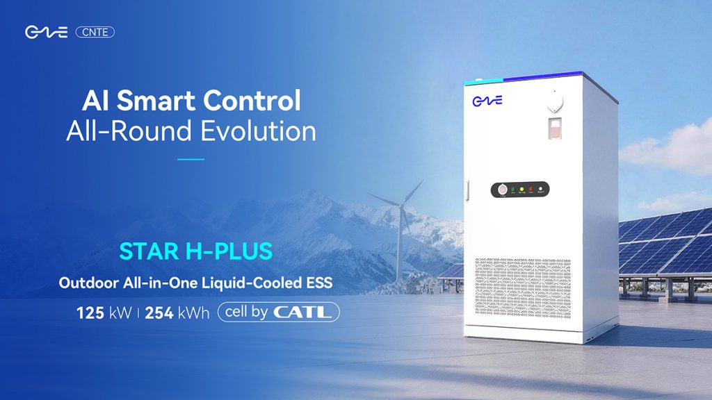
CNTE KEY ENERGY 2026 -tapahtumassa: Esittelee STAR H-PLUS ulkona käytettävän nestekäyttöisen energian varastointijärjestelmän
Mar 05, 2026 -
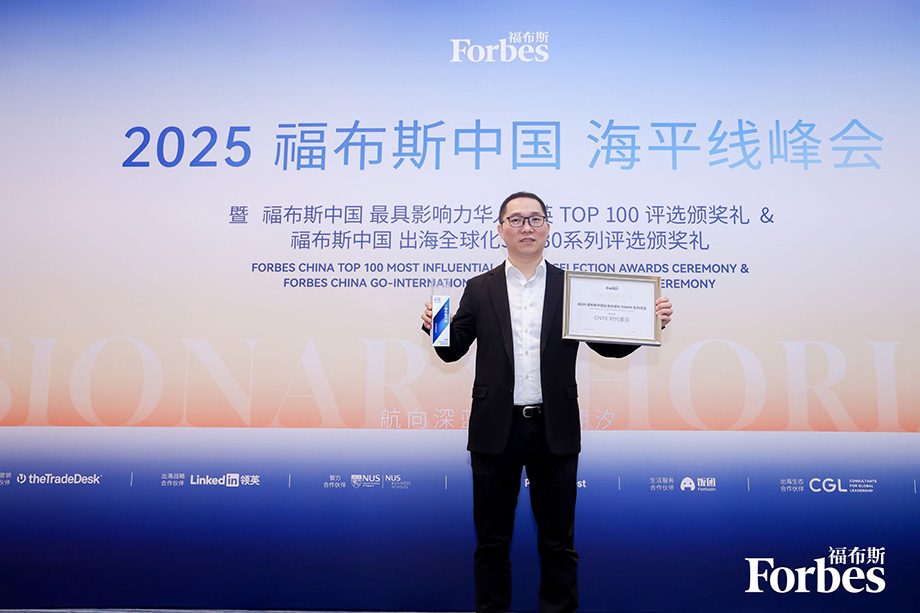
CNTE palkittu Forbes China 2025 johtavana maailmanlaajuisena brändinä
Jul 06, 2026 -
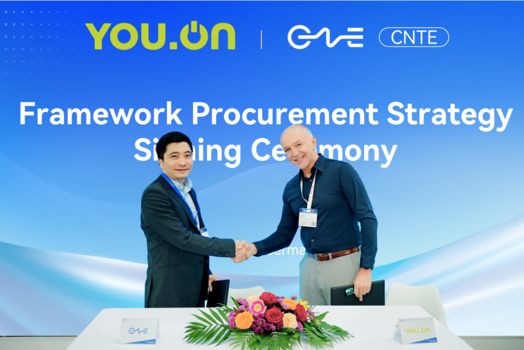
CNTE & YOU.ON tekevät yhteistyötä laajentaakseen varastointimarkkinoita
May 19, 2025 -
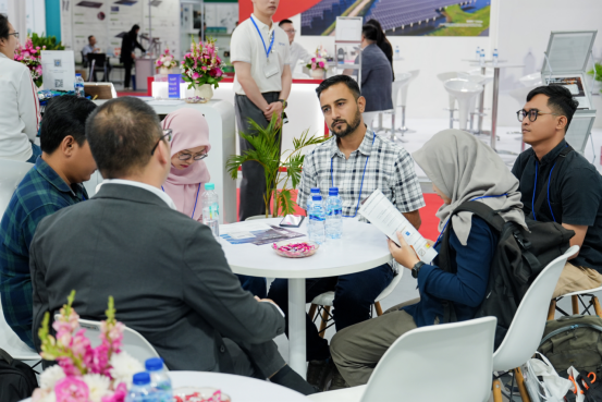
CNTE esittelee energian varastointisarjan Solartech 2025 -tapahtumassa
May 19, 2025 -
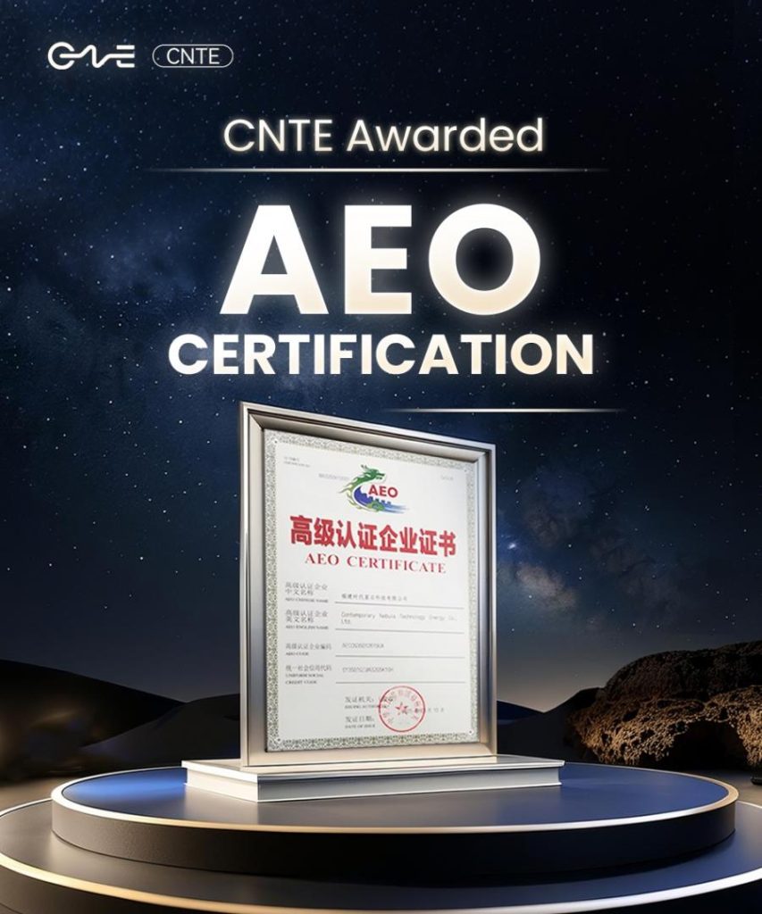
CNTE sai AEO-sertifikaatin
Jul 06, 2026 -
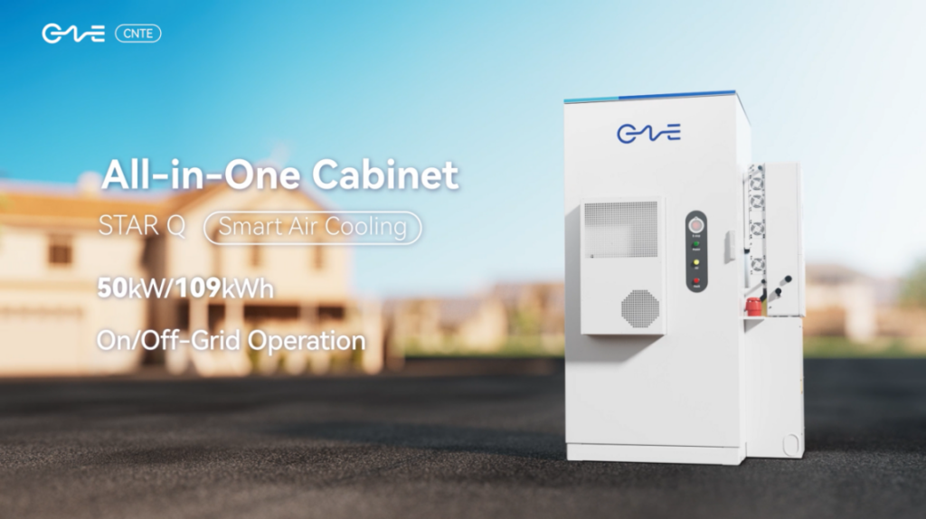
CNTE Uuden tuotteen lanseeraus STAR Q
Jan 15, 2025 -
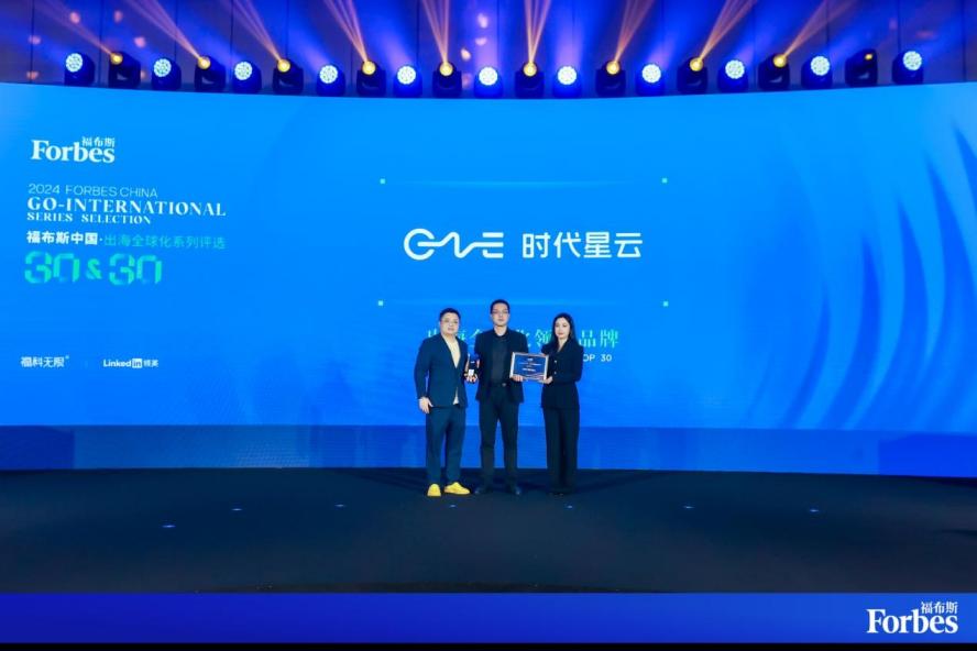
CNTE nimetty Forbes China 2024 Top 30 kansainvälisiksi brändeiksi
Jul 06, 2026
